A design method of pressure pulsation attenuator integrated in constant pressure variable pump

A constant pressure variable pump and pressure pulsation technology, which is applied to fluid pressure actuation devices, fluid pressure actuation system components, pump components, etc., can solve problems such as pipeline deformation, ring breakage, and hydraulic system hazards, and achieve improved design Quality and precision, small volume and quality, good attenuation effect

Active Publication Date: 2021-03-09
BEIHANG UNIV
View PDF8 Cites 0 Cited by
  • Summary
  • Abstract
  • Description
  • Claims
  • Application Information

AI Technical Summary

Problems solved by technology

[0002] Hydraulic systems are widely used in the aerospace field, mainly composed of hydraulic energy devices, control devices and actuators. Hydraulic pumps, as hydraulic energy devices, are mostly positive displacement pumps. The pressure pulsation will be generated after the system fluid resistance, which will cause harm to the hydraulic system. First, the sudden pressure pulsation under the sudden change of working conditions will directly cause the pipeline to deform or even break the ring. Many hydraulic components will also be damaged due to the instantaneous large pressure pulsation. Second, periodic pressure pulsation can also cause fatigue damage to pipelines or supporting structures; third, pressure pulsation can generate vibration and noise, which is harmful to human health

Method used


Image

  • A design method of pressure pulsation attenuator integrated in constant pressure variable pump
  • A design method of pressure pulsation attenuator integrated in constant pressure variable pump
  • A design method of pressure pulsation attenuator integrated in constant pressure variable pump

Examples


Embodiment

[0064] The design goal is: the rated displacement of a pump is 30 L / min, the rated pressure is 28MPa, the rated speed is 6000R / min; a hydraulic oil density is 900kg / m 3 , Volume elastic modulus 0.8 × 10 9 The PA, 40 ° C dynamic viscosity is 0.032Pa · s; the pressure pulse target amplitude is ± 1.4 MPa, and the maximum pressure drop value that can be accepted is 0.1 MPa.

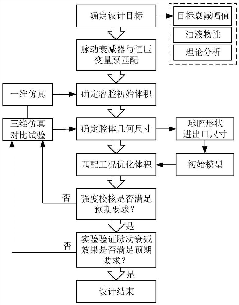
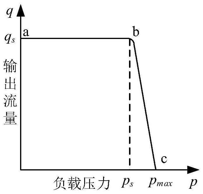
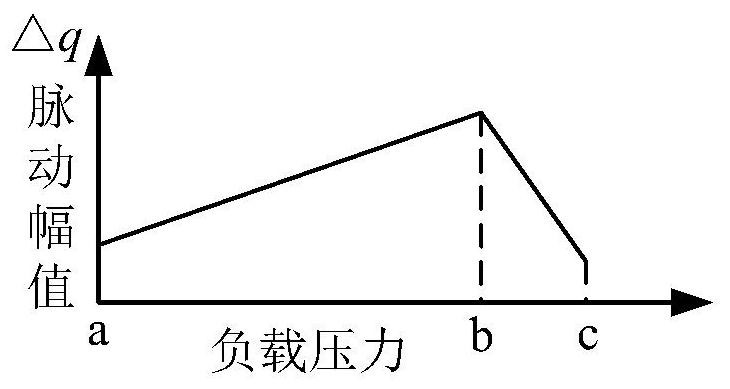
[0065] The pressure pulse attenuator matches the constant voltage variable pump, the flow match, according to the flow rate-pipe diameter requirements of the hydraulic system, the flow rate 30L / min high pressure hydraulic system corresponds to a minimum tube diameter of 8.9 mm, takes 9.5 mm; the pulsation magnitude is matched, according to the pulsation value The pump pressure-pulsating characteristic diagram, matching the maximum pressure pulse magnetic value; the pulsation frequency matches, the "hazard" matching of each speed is matched.

[0066] Determine the volume of the pulsation attenuator cavity,...


PUM


Abstract

The invention discloses a design method of a pressure pulsation attenuator integrated in a constant pressure variable pump, the steps are as follows: Step 1: determine the design target. Determine the working condition characteristics of the design object in the hydraulic system; Step 2: Match the pressure pulsation attenuator with the constant pressure variable pump, including flow matching, pulsation amplitude matching and pulsation frequency matching; Step 3: Determine the volume of the pressure pulsation attenuator cavity ; Step 4: Determine the geometric shape of the pulsation attenuator cavity; Step 5: Optimize the volume for matching working conditions; Step 6: Strength check and experimental verification. The method of the invention can directly attenuate the pulsation at the pulsation source without affecting other pipeline systems, has better attenuation effect, compact structure, and can reduce the volume of the entire hydraulic system. In the whole design process of the pressure pulsation attenuator, the present invention comprehensively uses theoretical calculation, one-dimensional and three-dimensional simulation and experimental verification methods to verify each other, which can improve the design quality and accuracy, and make the designed pressure pulsation attenuator model more feasible .

Description

Technical field [0001] The present invention relates to a pressure pulse attenuator design method, and more particularly to a pressure pulsating attenuator design method integrated into a constant voltage variable pump, which belongs to the field of pressure pulsation control of hydraulic system. Background technique [0002] The hydraulic system is widely used in the aerospace sector. It is mainly composed of hydraulic energy devices, control devices, and execution devices. The hydraulic pump is used as a hydraulic energy device, which is mostly a volumetric pump. The working principle determines the flow rate pulsation of cycle changes, and the flow rate is encountered. After the system is liquid, pressure pulsation will cause harm to hydraulic systems. First, the mutant pressure pulse is directly caused by the mutant pressure pulse, and many hydraulic components will be pulsed by the moment of large pressure pulsation. Damage; Second, periodic pressure pulsation can also cause...

Claims


Application Information

Patent Timeline
Patent Type & Authority Patents(China)
IPC IPC(8): F15B21/00F15D1/00F04B11/00
CPCF04B11/00F15B21/00F15D1/00
Inventor 王岩申同圣
Owner BEIHANG UNIV
Why Eureka
Try Eureka