Weak capacitance change measuring circuit of capacitance sensor

A capacitive sensor and weak capacitance technology, applied in the field of sensor measurement, can solve problems such as many constraints, and achieve the effects of strong adaptability, fast speed and high measurement accuracy

Pending Publication Date: 2020-06-05
BEIJING SINO CANBRIDGE MED TECH CO LTD
View PDF0 Cites 1 Cited by
  • Summary
  • Abstract
  • Description
  • Claims
  • Application Information

AI Technical Summary

Problems solved by technology

In addition, there is a high-voltage bilateral excitation detection method, which requires the use of high-frequency high-voltage excitation signals, which is only used for specific objects and occasions, and has many restrictions.

Method used


Image

  • Weak capacitance change measuring circuit of capacitance sensor
  • Weak capacitance change measuring circuit of capacitance sensor
  • Weak capacitance change measuring circuit of capacitance sensor

Examples


Embodiment 1

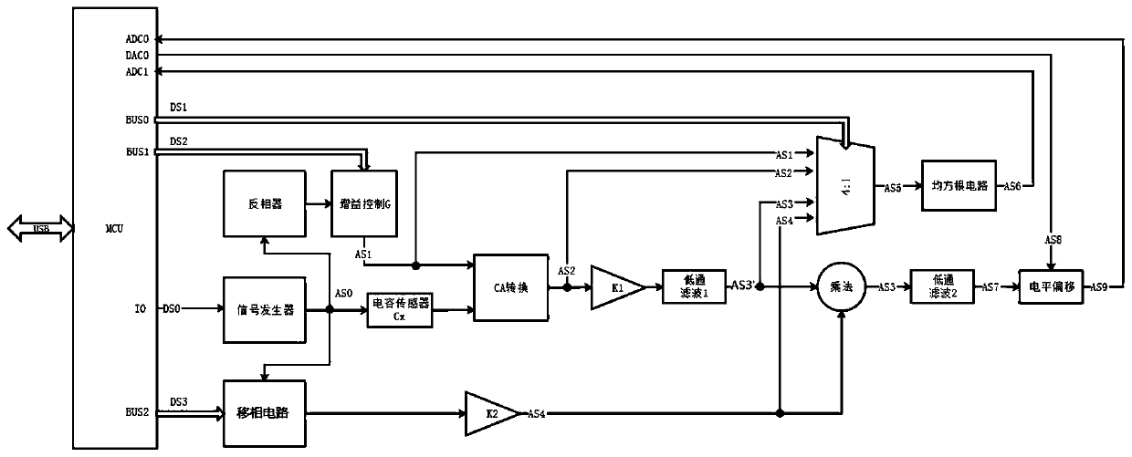
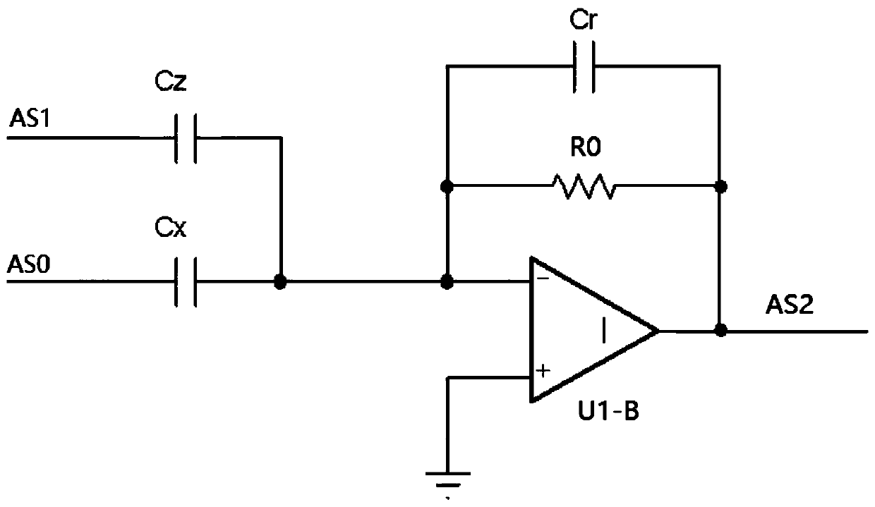
[0025] The capacitance-voltage conversion method used in the present invention is based on the AC negative feedback method of capacitance measurement, and a large number of improvements are made on this basis, so that the circuit directly outputs a DC voltage signal proportional to the relative change rate of capacitance. First, the capacitance change of the capacitive sensor (the change relative to the initial capacitance value) is transformed into the amplitude of a sine wave (excitation signal), which is proportional to the relative change rate of the capacitance of the capacitive sensor. After canceling the effect of the static capacitance of the capacitance sensor, the output of the CA conversion circuit only includes the capacitance variation of the capacitance sensor. The capacitance change is detected by an analog multiplier, and finally passes through a low-pass filter to output a DC signal proportional to the relative change rate of the sensor's capacitance. This cir...


PUM


Abstract

The weak capacitance change measuring circuit of the capacitance sensor comprises a single-chip microcomputer, a sine wave signal generator, a CA conversion circuit, a balancing circuit, an amplitudedemodulation circuit, a level offset circuit and a sampling feedback circuit. The sinusoidal signal generator converts a square wave signal output by the single-chip microcomputer into an excitation signal. The balance circuit converts the excitation signal into a balance signal of which the amplitude is controlled by the MCU and the phase is opposite to that of the excitation signal. The CA conversion circuit extracts an unbalanced signal which only reflects the capacitance variation of the capacitance sensor. The amplitude demodulation circuit resolves the amplitude of the unbalanced signaland then outputs the amplitude to the level offset circuit. The level offset circuit offsets the output signal, and finally a useful direct current signal is output. For a capacitance sensor with a static capacitance value within a certain range, the measuring circuit is automatically zeroed under the control of a single chip microcomputer, manual debugging is not needed, the measuring precision is high, and the conversion speed is high. The circuit is especially suitable for capacitance sensors with very weak capacitance changes.

Description

technical field [0001] The invention relates to the field of sensor measurement, in particular to a weak capacitance change measurement circuit of a capacitance sensor. Background technique [0002] The basic principle of a capacitive sensor is to convert a certain physical quantity, such as displacement, area, dielectric, etc., into capacitance, and then indirectly measure the desired physical quantity by measuring the capacitance. Capacitive sensors have a very wide variety of uses. Especially in the field of high-precision detection, capacitive sensors have an irreplaceable position. Capacitive sensors have the advantages of high sensitivity and fast response, but the measurement circuit is relatively complicated. In most cases, the capacitance change of the capacitive sensor is relatively weak, and the circuit is easily affected by its own parasitic parameters and environmental changes, which makes the problem more complicated. [0003] Common weak capacitance measure...

Claims


Application Information

Patent Timeline
Patent Type & Authority Applications(China)
IPC IPC(8): G01D5/24G05B19/042
CPCG01D5/24G05B19/0428G05B2219/2612G05B2219/2656
Inventor 吴远星何静宋军华王瑞林王洪超
Owner BEIJING SINO CANBRIDGE MED TECH CO LTD
Why Eureka
Try Eureka