Method for identifying plasma configuration based on image processing and probe data processing

A plasma and data processing technology, applied in plasma, electrical components, design optimization/simulation, etc., can solve problems such as large errors, optical path errors, fast probes and image transmission line interference, etc., to reduce noise and improve Accuracy, the effect of improving accuracy

Active Publication Date: 2020-06-05
XIDIAN UNIV
View PDF2 Cites 6 Cited by
  • Summary
  • Abstract
  • Description
  • Claims
  • Application Information

AI Technical Summary

Problems solved by technology

At present, east calculates the optical path by calculating the magnetic force lines to obtain the optical path of the far-infrared interferometer, which can provide an accurate optical path for the far-infrared laser interferometer, but the boundary of the plasma jet is not obvious, and the traditional method of determining the boundary is to observe a large number of jets. shape, or directly take the diameter of the nozzle as the optical path passed by the far-infrared laser interference system. This method of determining the boundary will cause a large error in the optical path. The reason is that when the plasma jet is ejected from the nozzle, the plasma Experience the expansion of the pressure difference or the instability of the air flow, which affects the configuration of the plasma jet, and thus affects the electron density of the far-infrared laser interference system to diagnose the plasma jet according to the traditional boundary determination method
This method of boundary determination will bring relatively large errors, which will affect the accuracy of far-infrared laser diagnosis of electron density.
[0005] To sum up, the problem existing in the existing technology is: the traditional way of determining the boundary is that the way of determining the boundary brings a relatively large error, which affects the accuracy of the far-infrared laser diagnosis of electron density
[0008] 2. The power supply device that generates the plasma jet usually brings electromagnetic radiation, which will interfere with the transmission line of the fast probe and the image
[0009] 3. The fast probe stays in the plasma for only 0.53s, and most of the time there is no plasma. How to accurately find out the suspension potential information of the fast probe

Method used


Image

  • Method for identifying plasma configuration based on image processing and probe data processing
  • Method for identifying plasma configuration based on image processing and probe data processing
  • Method for identifying plasma configuration based on image processing and probe data processing

Examples


Embodiment Construction

[0052] In order to make the object, technical solution and advantages of the present invention more clear, the present invention will be further described in detail below in conjunction with the examples. It should be understood that the specific embodiments described here are only used to explain the present invention, not to limit the present invention.

[0053] Aiming at the problems existing in the prior art, the present invention provides a method for identifying plasma configuration based on image processing and probe data processing. The present invention will be described in detail below with reference to the accompanying drawings.

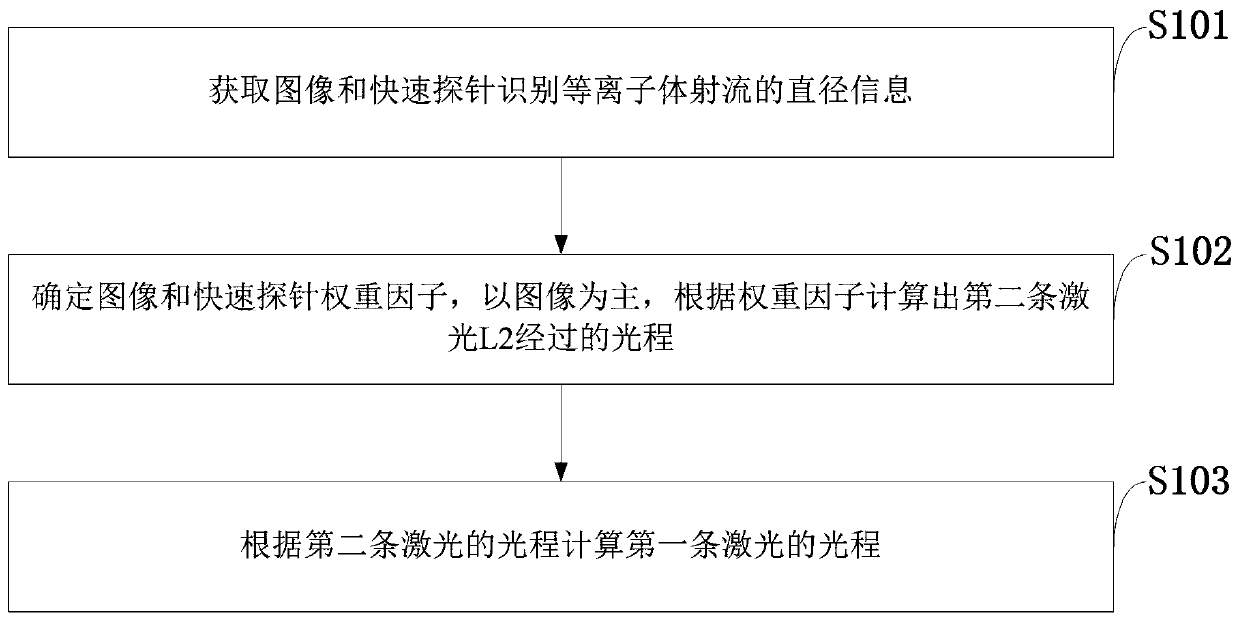
[0054] Such as figure 1 As shown, the method for identifying plasma configuration based on image processing and probe data processing provided by the embodiment of the present invention includes the following steps:

[0055] S101: Acquiring an image and identifying diameter information of a plasma jet by a fast probe.

[0056] S102: Dete...


PUM


Abstract

The invention belongs to the technical field of image recognition and signal analysis, and discloses a method for recognizing a plasma configuration based on image processing and probe data processing, and the method comprises the steps: carrying out the synchronous collection to obtain a plasma discharge video signal and a probe density curve at a continuous moment; extracting plasma boundary information from the plasma image information through an algorithm, extracting the time period of the plasma density from the rapid probe, and acquiring the radius of the jet flow through operation of time and acceleration; acquiring an image and identifying the diameter information of the plasma jet flow by a rapid probe; determining an image-image and a fast probe weight factor, and calculating anoptical path through which the second laser L2 passes by taking the image as a main part according to the weight factor; and calculating the optical path of the first laser according to the optical path of the second laser. According to the invention, the accuracy of the plasma boundary is improved, a reliable optical path is provided for HCN diagnosis of the jet electron density, and the accuracyof the electron density is improved.

Description

technical field [0001] The invention belongs to the technical field of image recognition and signal analysis, and in particular relates to a method for recognizing plasma configuration based on image processing and probe data processing. Background technique [0002] At present, the plasma wind tunnel can provide a pure, long-term stable high-enthalpy plasma jet, simulate the "black barrier" environment through the ICP jet wind tunnel, and can carry out research on the electromagnetic characteristics of the plasma sheath of hypersonic vehicles. The charged particles in the jet will absorb, reflect and scatter electromagnetic signals. Therefore, how to accurately diagnose the electron density in the jet plasma and understand the internal characteristics of the plasma jet play a key role in analyzing the "black barrier" environment. The far-infrared laser interferometry system has excellent performance in measuring the space-time distribution of plasma electron density. At pre...

Claims


Application Information

Patent Timeline
Patent Type & Authority Applications(China)
IPC IPC(8): G06F30/20H05H1/00
CPCH05H1/0043H05H1/0081Y02E30/10
Inventor 包为民张佳邓伟锋刘彦明欧阳文冲何宏伟王俊杰
Owner XIDIAN UNIV
Why Eureka
Try Eureka