System and method for laser nitriding treatment of metal surface

A metal surface, laser nitriding technology, applied in the direction of heat treatment equipment, heat treatment process control, metal material coating technology, etc., can solve the problems of high cost, high overall requirements, high requirements for personnel and matching, and achieve hardening The depth is easy to meet, the workers are easy to operate, and the effect of low labor intensity

Pending Publication Date: 2020-06-16
重庆金樾光电科技有限公司
View PDF7 Cites 4 Cited by
  • Summary
  • Abstract
  • Description
  • Claims
  • Application Information

AI Technical Summary

Problems solved by technology

Ion nitriding has the advantages of short production cycle, high surface hardness of parts, and the ability to control the brittleness of the nitrided layer. However, the manufacturing process of the ion nitriding furnace is very demanding, the materials used are also very particular, and the electrical control technology is very high. The overall requirements for personnel are high, not only the cost remains high, but also the requirements for personnel and supporting facilities are extremely high

Method used


Image

  • System and method for laser nitriding treatment of metal surface
  • System and method for laser nitriding treatment of metal surface
  • System and method for laser nitriding treatment of metal surface

Examples


Embodiment 1

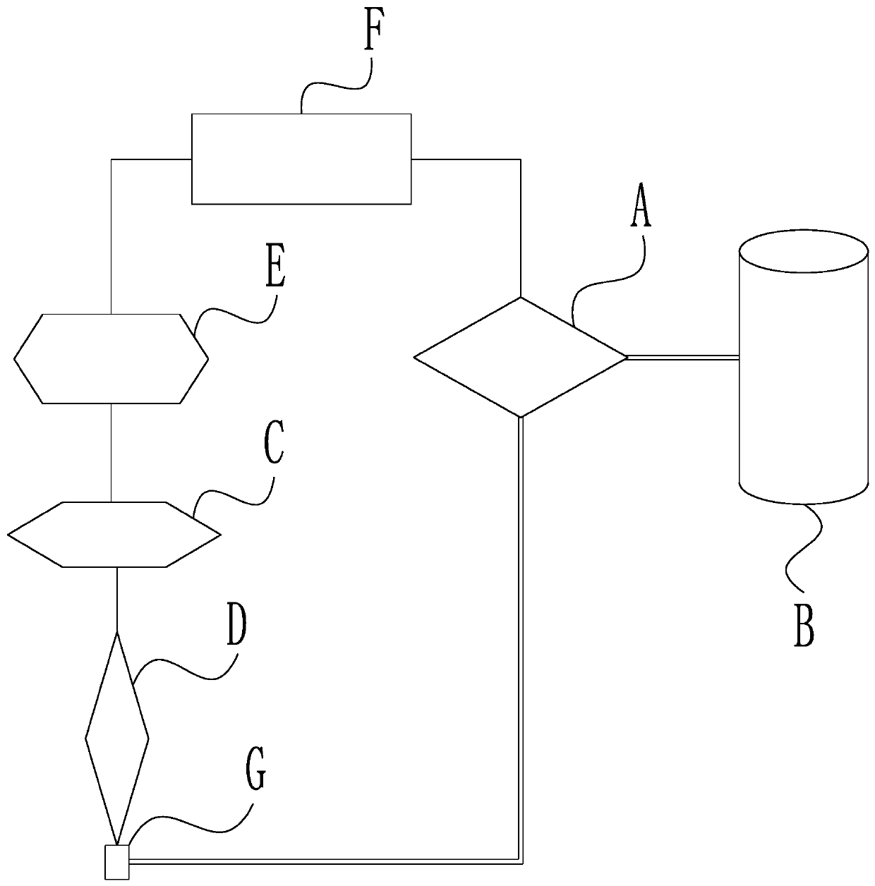
[0054] Embodiment 1: The laser spot emitted by the laser head D is a circular spot with a diameter of 0.4-1mm, the scanning power is 2000-4000W, and the continuous scanning speed is 100-200mm / min. Under this condition, the nitrogen is industrial nitrogen or high-purity nitrogen, preferably high-purity nitrogen. The feed rate of nitrogen gas is 30-80L / min, and the output pressure is 1.5-2MPa; the nitrogen atoms decomposed by laser irradiation are metallurgically bonded with the surface melted by laser heating, forming a nitride phase, and at the same time due to the self-cooling of the laser The blessing of hardening properties forms a composite layer of laser nitriding and quenching on the surface of the workpiece.

[0055] The surface of the workpiece treated by the laser nitriding and quenching composite process forms a nitrided and quenched composite layer with a thickness of 0.2-3mm, and the surface quality is good, without defects such as oxidation and decarburization. T...

Embodiment 2

[0056] Example 2: The laser spot emitted by the laser head D is a square spot with a side length of 2-4mm, the scanning power is 6000W, and the continuous scanning speed is 50mm / min, 80mm / min, 100mm / min, 150mm / min in three groups, Verify 400mm separately 2 . Under this condition, nitrogen adopts industrial high-purity nitrogen. The feed rate of nitrogen gas is 60-100L / min, and the output pressure is 0.5-1MPa; the nitrogen atoms decomposed by laser irradiation are metallurgically bonded with the surface melted by laser heating, forming a nitride phase, and at the same time due to the self-cooling of the laser The blessing of hardening properties forms a composite layer of laser nitriding and quenching on the surface of the workpiece.


PUM

PropertyMeasurementUnit
hardnessaaaaaaaaaa
thicknessaaaaaaaaaa
hardnessaaaaaaaaaa

Abstract

The invention discloses a system for laser nitriding treatment of a metal surface. The system comprises a gas distribution valve group, a nitrogen gas source, a laser generator, a laser head, a lasercontroller and a master control computer. The invention further discloses a method for laser nitriding treatment of the metal surface. The method is performed according to the following steps of S1, reccognizing the material of a to-be-treated workpiece; S2, cleaning the surface of the workpiece; S3, forming a nitrogen ring screen around a laser irradiation point; S4, irradiating laser to the laser irradiation point until a nitride layer is formed; and S5, adjusting the position of the laser head, and returning to the step 3. By adopting the above technical scheme, the advantages that the production period is short, the cost is low, combination between the nitride layer and a substrate is firm, deformation of the workpiece is small, the nitride layer is thick, the operation is simple, andthe requirement for quality of workers is not high are achieved.

Description

technical field [0001] The invention relates to the technical field of metal surface nitriding treatment, in particular to a system and method for laser nitriding treatment of metal surfaces. Background technique [0002] Metal surface nitriding treatment technology is a heat treatment process that puts the workpiece into a medium with a large amount of active nitrogen atoms, and infiltrates nitrogen atoms into the surface of the workpiece under a certain temperature and pressure to form a nitrogen-enriched hardened layer. Excellent hardness and wear resistance, but also improve the fatigue resistance and corrosion resistance of the workpiece. [0003] At present, the existing metal surface nitriding treatment technologies include gas nitriding, liquid nitriding and ion nitriding. [0004] Gas nitriding is to put the workpiece into a sealed space, pass through ammonia gas, heat it to 500-580°C for several hours to tens of hours, not only the time is long, but also if the me...

Claims


Application Information

Patent Timeline
Patent Type & Authority Applications(China)
IPC IPC(8): C21D1/09C21D1/62C23C8/24C21D11/00
CPCC21D1/09C21D1/62C23C8/24C21D11/00
Inventor 韦波夏凯苏杰
Owner 重庆金樾光电科技有限公司
Why Eureka
Try Eureka