Construction method for changing hollow floors into cast-in-situ floors under support

A technology of hollow-core slabs and cast-in-place slabs, which is applied in building maintenance, construction, and building construction. It can solve problems such as poor integrity, strength indicators that do not meet specification requirements, and poor durability. It meets the needs of renovation and has a long service life. , good shock resistance

Active Publication Date: 2020-06-16
NINGBO GUBANG BUILDING SPECIAL TECH
View PDF6 Cites 2 Cited by
  • Summary
  • Abstract
  • Description
  • Claims
  • Application Information

AI Technical Summary

Problems solved by technology

[0005] (1) The net height of the floor is reduced, and the comfort of the room is reduced;
[0006] (2) The durability of the floor slab is not improved;
[0007] (3) Integrity is poor
[0009] (1) Limitation 1: The code stipulates that after the reinforcement of reinforced concrete structural members, the increase in the flexural bearing capacity of the front section should not exceed 40%;
[0010] (2) Limitation 2: The code stipulates that the concrete strength level of the reinforced concrete structural members shall not be lower than C15, and the positive tensile bond strength of the concrete surface shall not be lower than 1.5MPa; due to the long service life of the hollow floor , its strength index often fails to meet the specification requirements;
[0011] (3) The requirements for the anchorage length at the end are relatively strict. In actual engineering, due to the limitation of the plate end support, the anchorage length is difficult to meet;
[0013] (5) Due to the long service life of the hollow floor slab, the carbonized layer on the surface is relatively thick, and the carbonized layer is often not fully polished when pasting the steel plate and carbon cloth, and the pasting quality is difficult to guarantee;
[0015] (7) Poor durability and poor aesthetics
[0016] In addition, in order to meet the new requirements for use, when it is necessary to open more and larger openings on the hollow floor and increase the load, it is difficult to meet the requirements of the above reinforcement methods.

Method used


Image

  • Construction method for changing hollow floors into cast-in-situ floors under support
  • Construction method for changing hollow floors into cast-in-situ floors under support
  • Construction method for changing hollow floors into cast-in-situ floors under support

Examples


Embodiment Construction

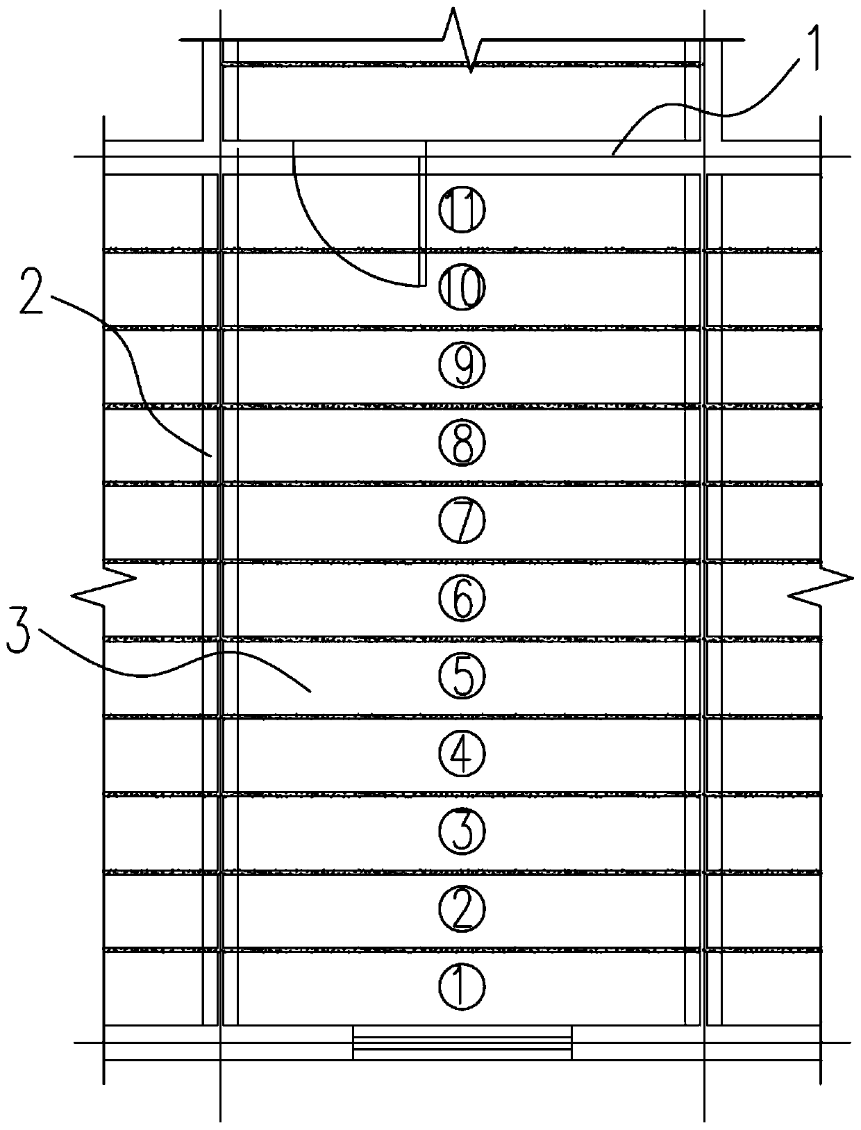
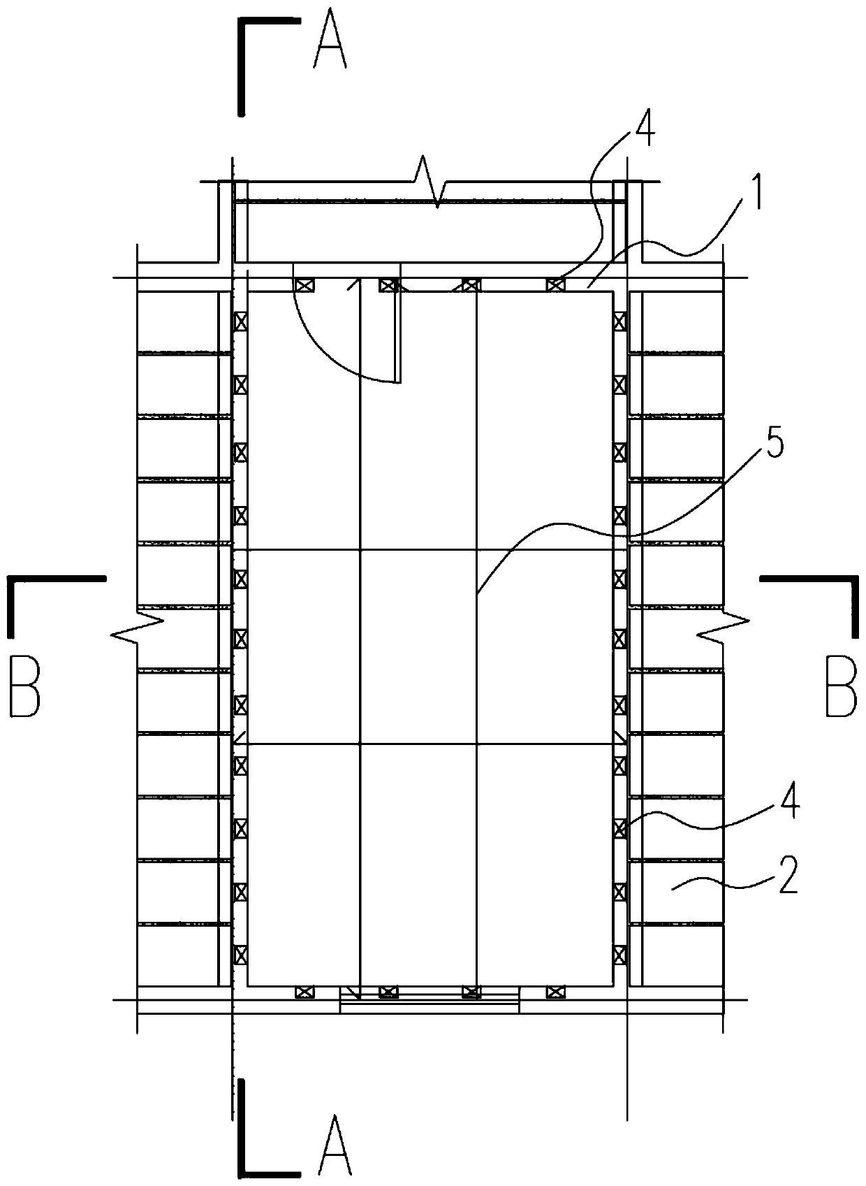
[0039] The present invention will be described in detail below in conjunction with accompanying drawing: Figures 1 to 4 As shown, the inventive hollow floor 3 is located on the load-bearing transverse wall 2 of the building, and the vertical wall 1 of the building is located on both sides of the hollow floor 3. The construction method includes the following steps:

[0040] S1. Set up a protective net under the hollow floor 3 to be removed; prevent the chiseled hollow floor from falling directly on the lower floor, reducing the impact on the floor;

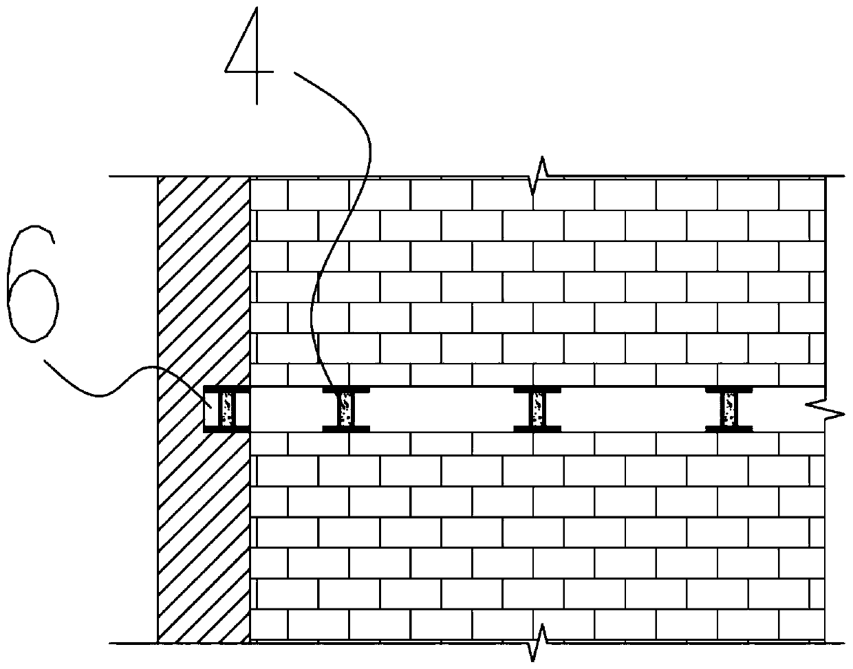
[0041] S2. Remove the hollow floor slabs 3 in the order of dismantling one at a time. The numbers of the hollow floor slabs 3 are ①, ②, ③, ④...; use the static cutting process to remove the first hollow floor slab 3, and replace the original hollow floor slab 3 Add a wall unloading support frame 4 in the middle of the gap between the support parts at both ends, and remove the hollow floor slabs 3 in sequence according to this step...


PUM


Abstract

The invention relates to a construction method for changing hollow floors into cast-in-situ floors under support. The construction method comprises the following steps that S1, a protective screen isarranged below to-be-disassembled follow floors; S2, the hollow floors are disassembled in a one-interval sequence, and one wall body disassembly support frame is additionally arranged at the middle part of each of supporting part gaps at the two ends of the original hollow floors; S3, a part of a wall body on a longitudinal wall flush with the hollow floors is removed through chiseling, and a plurality of uniformly distributed wall body discharge support frames are arranged; S4, rebars are mounted between the two corresponding wall body discharge support frames on a bearing cross wall, and then, rebars are mounted between the two corresponding wall body discharge support frames on the longitudinal wall; S5, a template is arranged; S6, staggered parts of the rebars are tightened through steel wires; and S7, the cast-in-situ floors are formed through concrete pouring. According to the construction method, the original hollow floors of which utilization functions after reconstruction cannot be met are changed into the cast-in-situ floors, and the reinforcement reconstruction purpose is achieved.

Description

technical field [0001] The invention belongs to the technical field of construction engineering reinforcement and transformation, and in particular relates to a construction method for underpinning a hollow floor to a cast-in-place floor. Background technique [0002] At present, the construction methods used for direct reinforcement of hollow floor slabs that do not meet the new use requirements are: such as enlarging the section method, bonding steel method, pasting carbon fiber cloth method, etc. [0003] The basic idea of ​​enlarging the section method is to increase the section of the floor slab on the top of the hollow slab to increase the bearing capacity and rigidity; The floor is jointly stressed to meet the new use requirements; the basic idea of ​​the paste carbon cloth method is to paste the carbon fiber cloth on the surface of the hollow floor through structural glue, so that the carbon fiber cloth and the original hollow floor are jointly stressed to meet the n...

Claims


Application Information

Patent Timeline
Patent Type & Authority Applications(China)
IPC IPC(8): E04G23/02
CPCE04G23/0237
Inventor 陈伟朱福祥江怡江超瑜毛善根楼驰江嘉伦李亮冯展万艺
Owner NINGBO GUBANG BUILDING SPECIAL TECH
Why Eureka
Try Eureka