Equipment cooling device

A cooling device and equipment technology, which is applied in the direction of air handling equipment, lighting and heating equipment, heating/cooling equipment, etc., and can solve the problems of compressor power increase and energy consumption increase

Inactive Publication Date: 2020-06-16
DENSO CORP
View PDF9 Cites 2 Cited by
  • Summary
  • Abstract
  • Description
  • Claims
  • Application Information

AI Technical Summary

Problems solved by technology

As a result, there is a problem that the amount of energy consumed by the refrigeration cycle for heating and cooling increases, such as an increase in the amount of electric power consumed by the compressor constituting the refrigeration cycle.

Method used


Image

  • Equipment cooling device
  • Equipment cooling device
  • Equipment cooling device

Examples


no. 1 approach

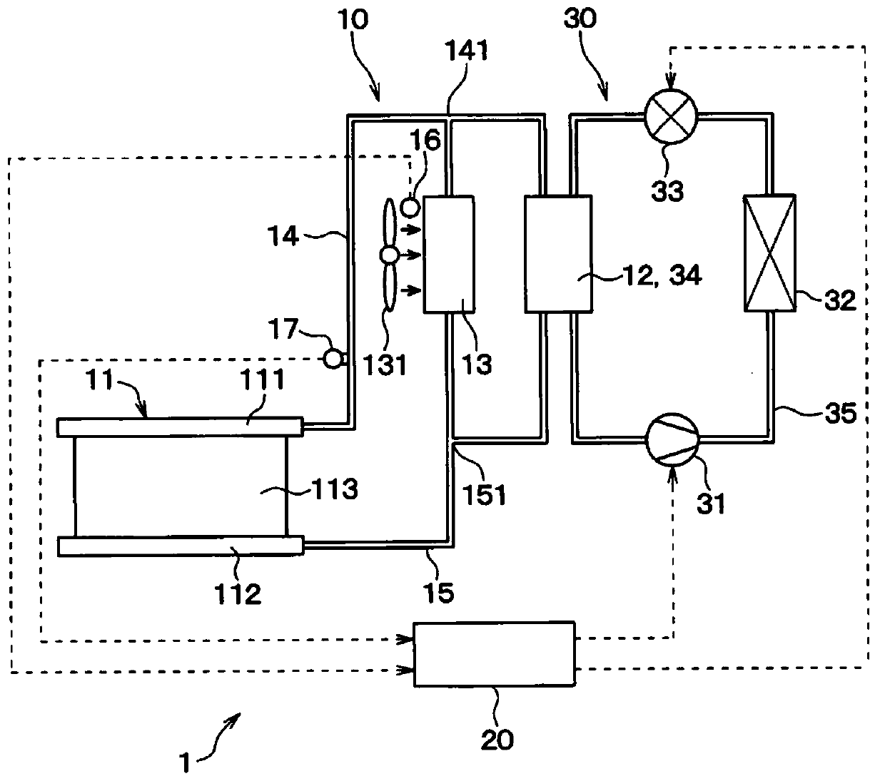
[0047] refer to Figure 1 to Figure 6 The first embodiment will be described. The equipment cooling device 1 of the first embodiment is mounted on an electric vehicle (hereinafter, simply referred to as a “vehicle”) such as an electric vehicle, a plug-in hybrid vehicle, or a hybrid vehicle. The target device to be cooled by the device cooling device 1 of the first embodiment is a secondary battery (hereinafter, referred to as "assembled battery 2") mounted on a vehicle.

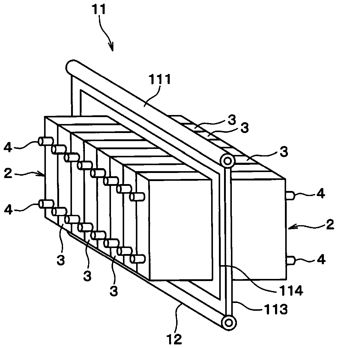
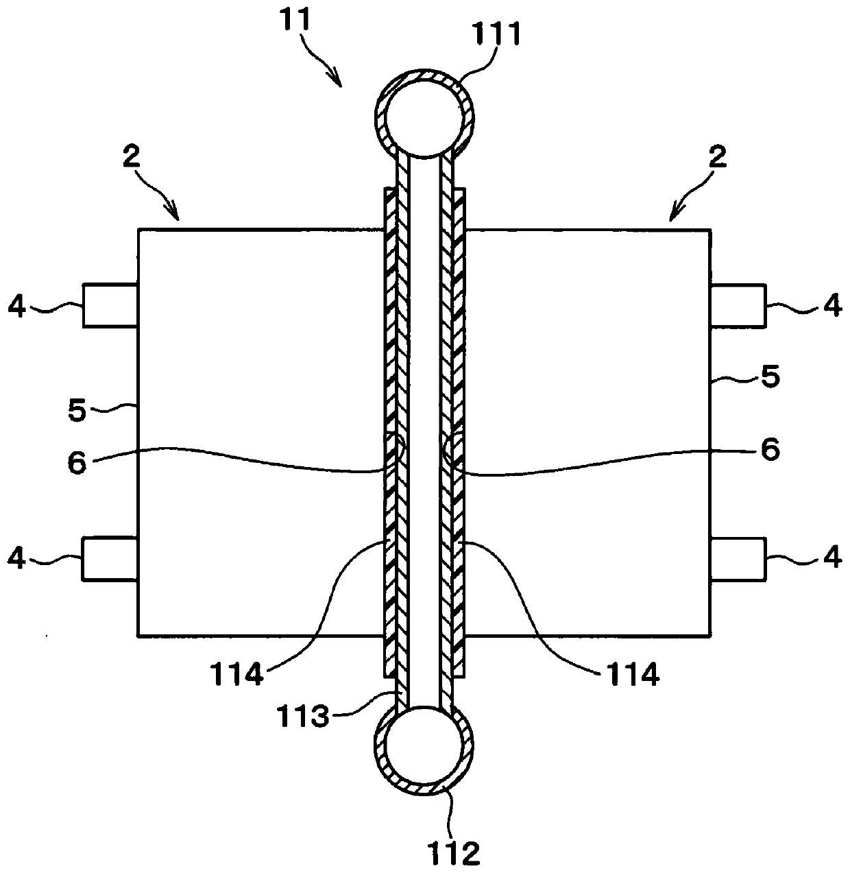
[0048] First, the assembled battery 2 to be cooled by the equipment cooling device 1 will be described. The large assembled battery 2 installed in a vehicle is a battery pack (ie, a power storage device) in which a plurality of battery packs are assembled, and is mounted under a seat or a luggage compartment of the vehicle. The electric power stored in the assembled battery 2 is supplied to the vehicle traveling motor via an inverter or the like. That is, the assembled battery 2 stores and discharges the e...

no. 2 approach

[0092] The second embodiment will be described. The second embodiment will specifically describe the configuration of the heat dissipation adjusting portion with respect to the first embodiment, and the other contents are the same as those of the first embodiment, so only the parts different from the first embodiment will be described.

[0093] The heat radiation amount adjustment unit included in the equipment cooling device 1 of the second embodiment is the compressor 31 included in the refrigeration cycle 30 . The compressor 31 serving as the heat radiation amount adjustment unit can be adjusted by reducing the rotation speed so that the flow rate of the refrigerant circulating in the refrigeration cycle 30 is reduced so that the refrigerant evaporator 34 (ie, the cold heat source heat exchanger 12 ) The heat dissipation amount of the working fluid flowing in it becomes small.

[0094] For the control process executed by the control device 20 included in the equipment cool...

no. 3 approach

[0099] A third embodiment will be described. In the third embodiment as well, the configuration of the heat radiation amount adjustment unit is specifically described with respect to the first embodiment, and the other contents are the same as in the first embodiment.

[0100] The heat radiation amount adjustment unit included in the equipment cooling device 1 of the third embodiment is the expansion valve 33 included in the refrigeration cycle 30 . The expansion valve 33 serving as the heat radiation amount adjusting portion can be adjusted by reducing the flow path area so that the heat radiation amount of the working fluid flowing in the refrigerant evaporator 34 (ie, the cold heat source heat exchanger 12 ) is reduced.

[0101] Figure 8 It is a graph showing the relationship between the degree of superheat of the refrigerant flowing out of the refrigerant evaporator 34 and the cooling capacity by the refrigerant evaporator 34 in the refrigeration cycle 30 . When the flo...


PUM


Abstract

A cooler (11) cools target equipment (2) by using latent heat from vaporization of a hydraulic fluid. A cold heat source-type heat exchanger (12) uses the cold heat of a low-temperature, low-pressurerefrigerant circulating through a freezing cycle (30), radiates heat from hydraulic fluid that has vaporized in a cooler (11), and condenses the hydraulic fluid. An air cooled heat exchanger (13) usescold heat of external air, radiates heat from hydraulic fluid that has vaporized in the cooler (11), and condenses the hydraulic fluid. The cooler (11), the cold heat source-type heat exchanger (12),and the air cooled heat exchanger (13) are connected by a gas pipe (14) and a liquid pipe (15). An external air temperature detection unit (16) detects external air temperature. A saturation temperature detection unit (17) detects the saturation temperature of hydraulic fluid circulating through a thermosiphon circuit (10). Heat radiation amount adjustment units (18, 20, 31, 33, 38, 41, 321, 322)adjust the amount of heat radiation from the hydraulic fluid flowing through the cold heat source-type heat exchanger (12), such that the saturation temperature of the hydraulic fluid is higher thanthe external air temperature.

Description

[0001] Cross-referencing of related applications [0002] This application is based on Japanese Patent Application No. 2017-211970 filed on November 1, 2017, the contents of which are incorporated herein by reference. technical field [0003] The present invention relates to a device cooling device for cooling a target device by a thermosyphon circuit. Background technique [0004] Conventionally, there has been known a facility cooling device that cools a target facility to be cooled by an annular thermosyphon circuit. [0005] The thermosiphon circuit included in the cooling device described in Patent Document 1 is obtained by connecting a cooler for performing heat exchange between the target equipment and the working fluid and two condensers for condensing the working fluid evaporated in the cooler through piping. of. One of the two condensers is an air-cooled heat exchanger that exchanges heat between the outside air and the working fluid. The other condenser is a co...

Claims


Application Information

Patent Timeline
Patent Type & Authority Applications(China)
IPC IPC(8): F25B1/00B60H1/32F28D15/02H01M10/613H01M10/615H01M10/625H01M10/633H01M10/6556H01M10/6569H05K7/20
CPCH01M10/613H01M10/625H05K7/20F25B1/00F28D15/02H01M10/6561H01M10/635Y02E60/10H01M2220/20B60H1/00278B60H2001/00307B60H1/32281H01M10/6556H01M10/6568
Inventor 三浦功嗣大见康光义则毅竹内雅之
Owner DENSO CORP
Why Eureka
Try Eureka