
Heat exchanger and manufacturing method thereof

A manufacturing method and heat exchanger technology, applied in heat exchange equipment, lighting and heating equipment, tubular elements, etc., can solve the problems of low heat exchange efficiency, achieve the effects of improving heat exchange efficiency, increasing disturbance, and increasing contact area

Pending Publication Date: 2020-06-19
GUANGZHOU INST OF RAILWAY TECH
View PDF0 Cites 0 Cited by
  • Summary
  • Abstract
  • Description
  • Claims
  • Application Information

AI Technical Summary

Problems solved by technology

[0005] In order to overcome the defects of low heat exchange efficiency in the above-mentioned prior art, the present invention provides a heat exchanger and its manufacturing method, which effectively improves the heat exchange efficiency

Method used


Image

  • Heat exchanger and manufacturing method thereof
  • Heat exchanger and manufacturing method thereof
  • Heat exchanger and manufacturing method thereof

Examples


Embodiment 1

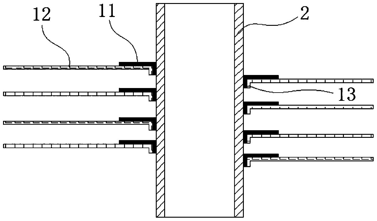
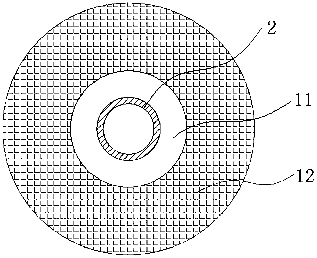
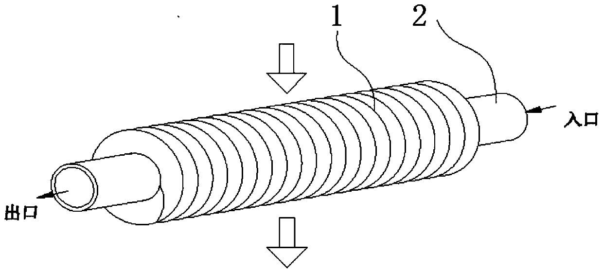
[0029] Such as Figure 1 to Figure 4 As shown, a heat exchanger includes a heat exchange tube 2, and a spiral coil 1 is wound on the outer wall of the heat exchange tube 2; the coil 1 includes a metal sheet 11 and a wire mesh 12, and the The wire mesh 12 is fixed on the surface of the metal sheet 11. The wire mesh 12 greatly increases the contact area of ​​fluids such as air, and can also increase the disturbance when fluids such as air flow through, which will significantly enhance the heat exchange efficiency.

[0030] In this embodiment, the wire mesh 12 is fixed on the surface of the thin metal plate 11 by diffusion welding. The wires of the wire mesh 12 are connected to each other by diffusion welding to form an integral body; the wires of the wire mesh 12 and the wire mesh 12 and the thin metal plate 11 are formed into a whole by diffusion welding At the same time, it is connected with the outer wall of the heat exchange tube 2 by an interference fit, which can ensure ...

Embodiment 2

[0036] This embodiment provides a method for manufacturing a heat exchanger, comprising the following steps:

[0037] S1. According to the design and performance requirements of the heat exchanger, determine the overall structure and size of the heat exchanger, including the diameter and length of the heat exchange tube 2, as well as the outer diameter, spacing and number of winding turns of the winding sheet 1;

[0038]S2. Determine the materials of the wire mesh 12 and the smooth metal sheet 11 according to the requirements of the heat exchanger. The wire mesh 12 and the metal sheet 11 generally use the same type of material, and the materials can be copper or copper alloy, aluminum or aluminum alloy, Steel or stainless steel, etc.;

[0039] S3. Determine the shape, size and thickness of the wire mesh 12 and the metal sheet 11 according to the outer diameter of the winding sheet 1, the spacing and the number of winding turns, and the wire mesh 12 and the metal sheet 11 are e...


PUM


Abstract

The invention belongs to the technical field of heat exchangers, and particularly relates to a heat exchanger and a manufacturing method thereof. The heat exchanger comprises a heat exchange tube, wherein a winding sheet is spirally wound on the outer wall of the heat exchange tube; the winding sheet comprises a metal sheet and a metal wire mesh; and the metal wire mesh is fixed on the surface ofthe metal sheet. According to the heat exchanger and the manufacturing method thereof, the winding sheet adopts a composite structure of the metal wire mesh and the metal sheet, the contact area of fluids such as air is greatly increased by the metal wire mesh, the disturbance of the fluids such as air when flowing through can be increased, and the heat exchange efficiency can be remarkably enhanced. The metal wire mesh and the metal sheet are welded into a whole in a diffusion mode, and the metal wire mesh and metal sheet composite structure plate is tightly wound on the heat exchange tube byadopting a winding machine, so that the tight contact between the metal sheet and the metal wire mesh and the wall of the heat exchange tube can be guaranteed, the heat resistance between the heat exchange tube and the winding sheet is reduced, and the heat exchange efficiency is improved.

Description

technical field [0001] The invention belongs to the technical field of heat exchangers, and more specifically relates to a heat exchanger and a manufacturing method thereof. Background technique [0002] A heat exchanger, also known as a heat exchanger, is an energy-saving device that transfers heat between materials between two or more fluids at different temperatures. It transfers heat from a fluid with a higher temperature to a fluid with a lower temperature. Fluid, to make the fluid temperature reach the index specified in the process to meet the needs of process conditions, and it is also one of the main equipment to improve energy utilization. Heat exchangers play an important role in petroleum, chemical industry, metallurgy, heating, refrigeration and air conditioning, machinery, food, pharmaceuticals, energy power, pressure vessels and many other industrial productions. In engineering applications, heat exchangers can be used as heaters, cooling Condensers, condense...

Claims


Application Information

Patent Timeline
Patent Type & Authority Applications(China)
IPC IPC(8): F28F1/36F28F21/08
CPCF28F1/36F28F21/082F28F21/083F28F21/084F28F21/085
Inventor 陈舒萍
Owner GUANGZHOU INST OF RAILWAY TECH
Learn More