Lining assembly and reaction chamber

A technology of lining components and reaction chambers, which is applied in the fields of electrical components, semiconductor/solid-state device manufacturing, discharge tubes, etc., can solve problems such as high product cost, complex structure, and eccentric etching results, so as to reduce product production costs, The effect of improving angular uniformity and reducing production costs

Active Publication Date: 2020-06-19
BEIJING NAURA MICROELECTRONICS EQUIP CO LTD
View PDF5 Cites 0 Cited by
  • Summary
  • Abstract
  • Description
  • Claims
  • Application Information

AI Technical Summary

Problems solved by technology

However, because the inner lining needs to have holes or grooves to meet the needs of observation, film transfer and pumping, the distribution of plasma current on the surface of the inner lining is uneven, and the uneven plasma current will affect the plasma density in the base. The uniformity of the radial distribution of the slices, which in turn leads to problems such as eccentricity of the etching results
[0003] In order to solve the problem of uneven distribution of plasma, such as figure 1 As shown, the prior art provides a dual-output coil design, which realizes the uniformity of plasma distribution on the wafer surface by controlling the shape of the coil and the current ratio of the inner and outer rings.
Although the existing technology can solve the problem of plasma distribution eccentricity, it has high requirements for coil structure distribution and matching current ratio control, which leads to complex structure and high product cost

Method used


Image

  • Lining assembly and reaction chamber
  • Lining assembly and reaction chamber
  • Lining assembly and reaction chamber

Examples


Embodiment Construction

[0026] In order for those skilled in the art to better understand the technical solution of the present invention, the lining assembly and the reaction chamber provided by the present invention will be described in detail below with reference to the accompanying drawings.

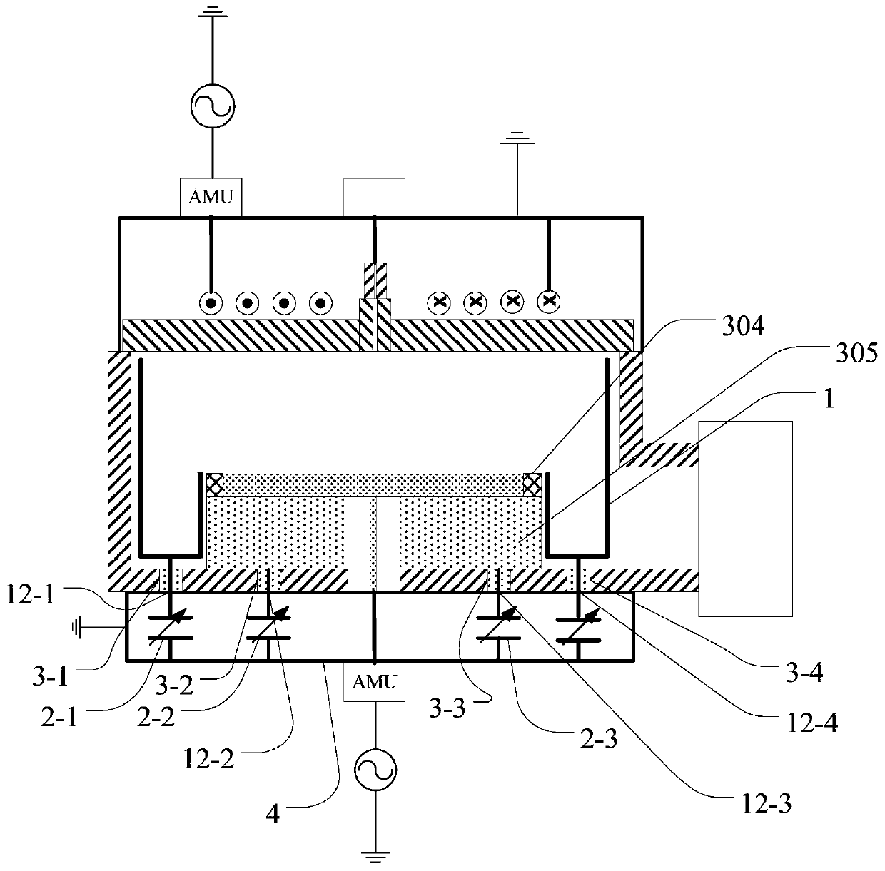
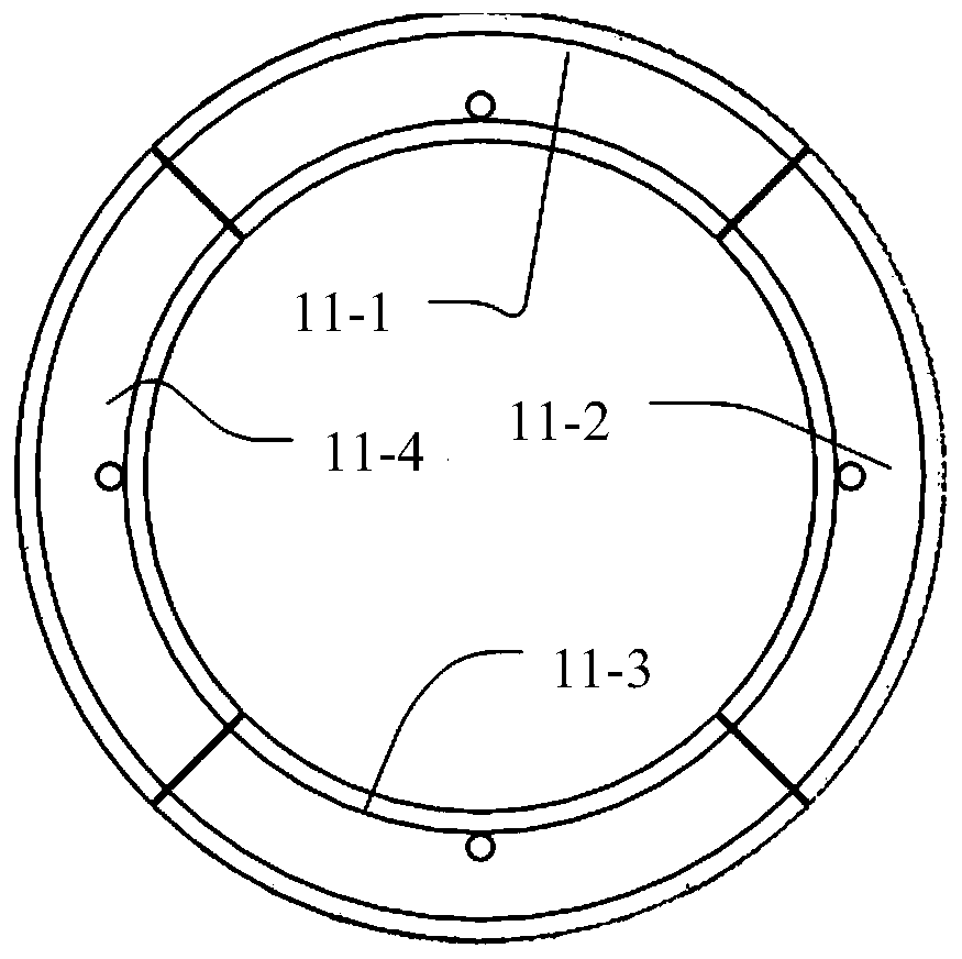
[0027] figure 2 It is a schematic structural view of a reaction chamber provided by an embodiment of the present invention, and FIG. 3 is a schematic structural view of a liner used in a liner assembly provided by an embodiment of the present invention. please combine figure 2 3, the first embodiment of the present invention provides a liner assembly, including a liner 1 and a plurality of adjustment units 2, wherein the liner 1 is used to surround the inside of the side wall of the reaction chamber, and the liner 1 includes A plurality of sub-liners 11 (11-1, 11-2, 11-3, 11-4) corresponding to a plurality of adjustment units 2 (2-1, 2-2, 2-3, 2-4), A plurality of sub-liners 11 (11-1, 11-2, 11-3, 11-4) ...


PUM


Abstract

The invention provides a lining assembly and a reaction chamber. The lining assembly comprises a lining and a plurality of adjusting units, the lining is used for surrounding the inner side of a sidewall of the reaction chamber, the lining comprises a plurality of sub-linings in one-to-one correspondence with the adjusting units, the sub-linings are arranged at intervals in the circumferential direction, the first end of each adjusting unit is connected with the corresponding sub-lining, and the second end of each adjusting unit is used for being grounded; and capacitance values of the plurality of adjusting units are set to enable capacitive reactance of the plurality of sub-liners to be equal. By arranging the adjusting unit, the capacitive reactance of the plurality of sub-linings is equal, and then the currents flowing through the sub-linings are equal, so that the plasma densities in the angles corresponding to the sub-linings are the same, and the angular uniformity of the plasmas is improved. Moreover, the lining assembly provided by the invention is simple in structure and easy to control, and the production cost of products is reduced.

Description

technical field [0001] The invention belongs to the technical field of semiconductor manufacturing, and in particular relates to a lining component and a reaction chamber. Background technique [0002] Inductively coupled plasma (ICP) is a commonly used plasma source for dry etching and thin film deposition in the semiconductor field. ICP applies high-frequency current to the surface of the coil to generate an alternating high-frequency electromagnetic field to excite the gas to generate plasma, and the coil and the discharge gas are separated by a dielectric window. When ICP is applied to the etching process, in order to improve the maintenance convenience of the chamber and prevent the corrosion of chamber materials, a lining structure is usually used. The lining needs to be grounded to ensure that the ICP electrodes and bias electrodes have Stable reference electrode. However, because the inner lining needs to have holes or grooves to meet the needs of observation, film...

Claims


Application Information

Patent Timeline
Patent Type & Authority Applications(China)
IPC IPC(8): H01J37/32H01L21/67
CPCH01J37/32477H01L21/67069H01J2237/334
Inventor 李兴存光娟亮
Owner BEIJING NAURA MICROELECTRONICS EQUIP CO LTD
Why Eureka
Try Eureka