
Equipment regulation and control device of comprehensive energy system

A technology of an integrated energy system and a control device, applied in the field of equipment control devices of an integrated energy system, can solve problems such as resource waste, energy loss, soil problems, etc., and achieve the effect of saving energy and reducing pollution

Active Publication Date: 2020-06-19
GUIZHOU POWER GRID CO LTD
View PDF5 Cites 1 Cited by
  • Summary
  • Abstract
  • Description
  • Claims
  • Application Information

AI Technical Summary

Problems solved by technology

[0004] There are differences in the conversion rate, stability, safety, geographical influence, technical requirements, impact on the environment and cost of different energy sources. For example, water energy is affected by rainfall, and the production capacity is stable and the benefits are large in the stage of heavy rainfall. The dry season is extremely unstable; clean natural energy sources such as solar energy and wind energy also have the same problem; biomass energy, natural gas, oil and other energy sources have stable production capacity, but they will cause soil problems, environmental pollution, resource waste, etc. to varying degrees. 1. There are differences in the demand for electricity, heat and cold in different regions. While coordinating the transformation of various energies, a certain amount of energy loss will be generated. The current comprehensive energy system cannot make targeted adjustments according to these factors. Under the circumstances, adjust the energy production efficiency and reduce the damage to the environment

Method used


Image

  • Equipment regulation and control device of comprehensive energy system
  • Equipment regulation and control device of comprehensive energy system
  • Equipment regulation and control device of comprehensive energy system

Examples


Embodiment 1

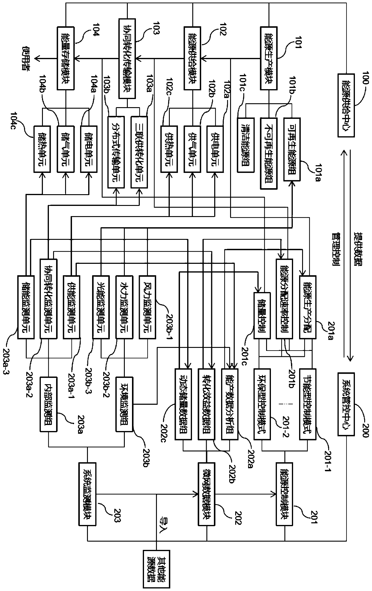
[0038] Reference Figure 1~6 , Is a specific embodiment of the present invention, this embodiment provides an integrated energy system equipment control device, by setting different categories according to energy characteristics, when conditions are met, adding specific energy such as energy-saving energy or clean energy The use of energy, while changing the rate of production and supply of various types of energy, in order to achieve the purpose of saving energy and protecting the environment.

[0039] Specifically, the equipment control device of the integrated energy system includes an energy supply center 100 and a system management and control center 200 that controls the operation of each module of the energy supply center 100. The energy supply center 100 provides a supply process from energy output to distribution, depending on whether the energy is With the characteristics of sustainable use, energy can be divided into two categories: renewable energy and non-renewable e...

specific Embodiment approach 1

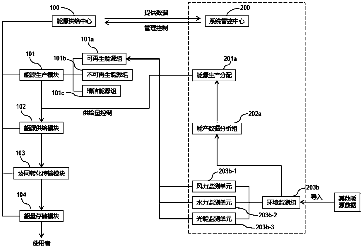
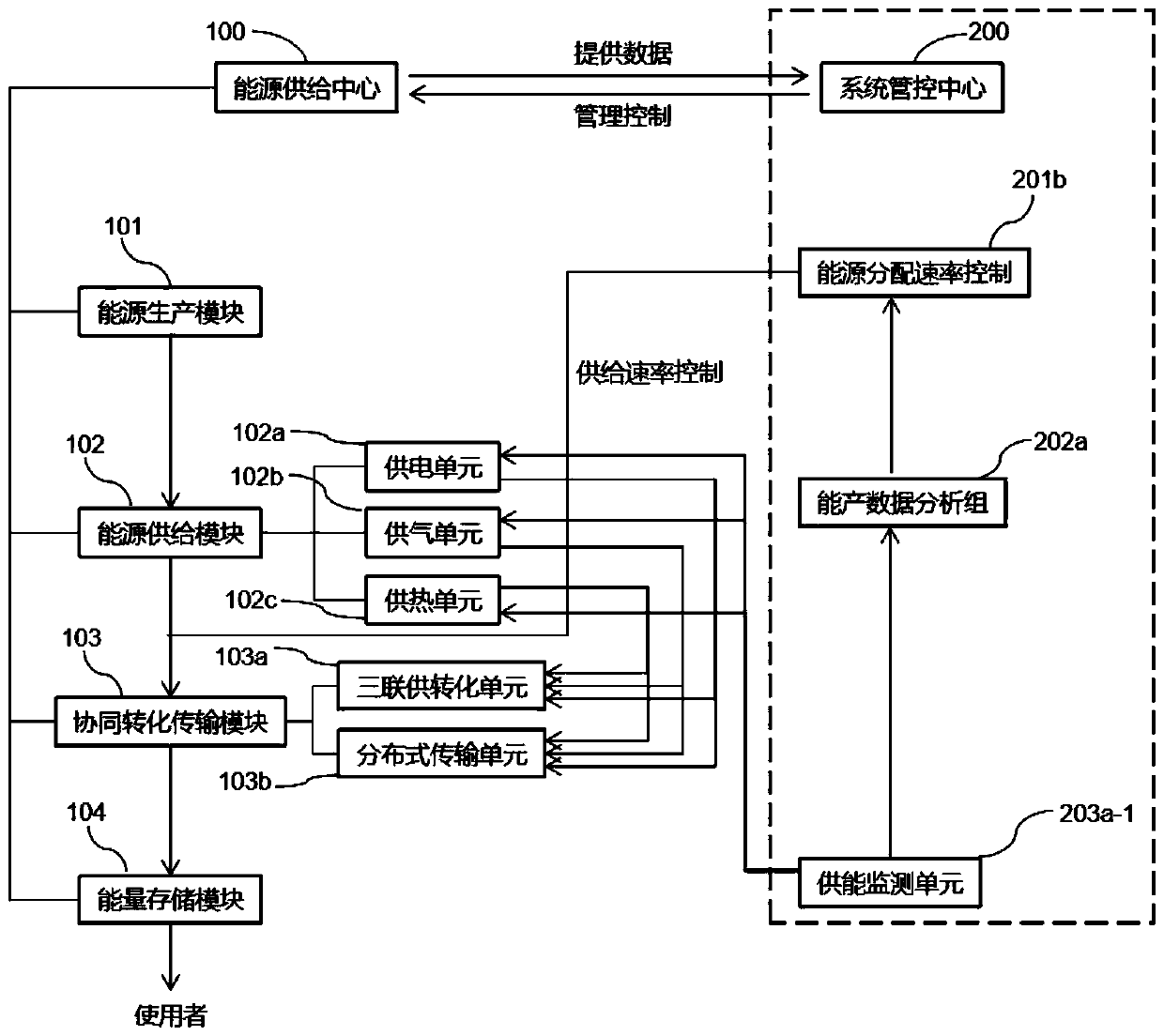
[0054] Under the control of the integrated energy system, such as figure 2 As shown, according to the monitoring of the wind monitoring unit 203b-1, hydraulic monitoring unit 203b-2 and light monitoring unit 203b-3 in the environmental monitoring group 203b in the system monitoring module 203, relevant data is sent to the microgrid data module 202, and the microgrid The data module 202 builds a data model based on the data it provides to understand the energy production rate of the renewable energy group 101a under the energy production module 101. The energy production allocation 201a makes a judgment based on the data. If the energy production rate of the renewable energy group 101a is higher And it can be supplied stably, the energy-saving control mode 201-1 is adopted. The energy supply monitoring unit 203a-1 monitors the energy supply rate of each energy in the energy supply module 102, and sends it to the energy production data analysis group 202a to establish a production...

specific Embodiment approach 2

[0056] As shown in the figure, based on the energy-saving control mode 201-1 adopted in the first embodiment, this embodiment takes the standard environmentally-friendly control mode 201-2 as the second embodiment.

[0057] Similarly, under the control of the integrated energy system, such as figure 2 According to the monitoring of the wind monitoring unit 203b-1, hydraulic monitoring unit 203b-2 and light monitoring unit 203b-3 in the environmental monitoring group 203b in the system monitoring module 203, send relevant data to the microgrid data module 202, the microgrid data module 202 builds a data model based on the data provided by it to understand the energy production rate of the renewable energy group 101a under the energy production module 101. Energy production allocation 201a makes a judgment based on the data. If the energy production rate of the renewable energy group 101a is low or the supply is not available If it is stable, the standard environmentally friendly c...


PUM


Abstract

The invention discloses an equipment regulation and control device of a comprehensive energy system. The equipment regulation and control device comprises an energy supply center and a system management and control center for controlling all modules of the energy supply center to operate. The energy supply center provides a supply process from energy output to dispatch and use and at least comprises an energy production module, an energy supply module used for transmitting all output energy, a cooperative conversion transmission module and an energy storage module, wherein the energy production module can be at least divided into a renewable energy group and a non-renewable energy group; the system management and control center at least comprises an energy control module which controls conversion and distribution of each energy source in the energy source production module. Multiple groups of energy classifications are set according to the energy characteristics, the supply amount of each type of energy is controlled according to the productivity benefit of each energy monitored in real time, and the energy is saved and the environmental pollution is weakened by improving the energy production amount and the supply rate of clean and energy-saving types under the condition of conforming to the use conditions.

Description

Technical field [0001] The invention relates to the technical field of integrated energy systems, in particular to an equipment control device of an integrated energy system. Background technique [0002] The integrated energy system refers to the use of advanced physical information technology and innovative management models in a certain area to integrate multiple energy sources such as coal, oil, natural gas, electric energy, and thermal energy in a certain area to achieve coordinated planning between multiple heterogeneous energy subsystems. This new type of integrated energy system must effectively improve energy utilization efficiency and promote sustainable energy development while meeting the diversified energy demand within the system. [0003] The integrated energy system includes clean energy power generation such as gas turbines and photovoltaics, gas boilers, and energy production equipment such as higher-level power grids; energy conversion equipment such as heat pump...

Claims


Application Information

Patent Timeline
Patent Type & Authority Applications(China)
IPC IPC(8): H02J3/00H02J3/28H02J3/38G06Q10/06G06Q50/06
CPCG06Q10/06312G06Q50/06H02J3/00H02J3/28Y02E40/70Y02E70/30Y04S10/50Y02P90/82
Inventor 唐学用赵庆明李庆生邓朴郭作刚何向刚张裕孙斌贺墨琳钟以林刘影方学智
Owner GUIZHOU POWER GRID CO LTD
Learn More