
Fluidized bed combustion device for ammonia gas, power generation system and combustion method of ammonia gas

A combustion device and power generation system technology, which is applied to fluidized bed combustion equipment, combustion methods, fuels burned in a molten state, etc., can solve problems such as slow combustion rate, low combustion rate, and difficult ignition of ammonia gas, and achieve improved combustion intensity and efficiency, avoid flashback and explosion, and realize the effect of stable combustion

Inactive Publication Date: 2020-06-23
QINGDAO INST OF BIOENERGY & BIOPROCESS TECH CHINESE ACADEMY OF SCI
View PDF8 Cites 2 Cited by
  • Summary
  • Abstract
  • Description
  • Claims
  • Application Information

AI Technical Summary

Problems solved by technology

[0005] The main purpose of the present invention is to solve the problems that ammonia gas is difficult to ignite, has low combustion rate, unstable combustion flame, and is difficult to be used for large-scale power generation, because compared with methane and other gases, the minimum ignition energy of ammonia gas is higher, resulting in It is not easy to be ignited, and the reactivity of ammonia and oxygen is relatively weak, resulting in a relatively slow burning rate

Method used


Image

  • Fluidized bed combustion device for ammonia gas, power generation system and combustion method of ammonia gas
  • Fluidized bed combustion device for ammonia gas, power generation system and combustion method of ammonia gas
  • Fluidized bed combustion device for ammonia gas, power generation system and combustion method of ammonia gas

Examples


Embodiment Construction

[0064] It should be noted that unless otherwise specified, all technical and scientific terms used in the present invention have the same meaning as commonly understood by one of ordinary skill in the art to which this invention belongs.

[0065] It should be noted that the terminology used in the present invention is only for describing specific embodiments, and is not intended to limit the exemplary embodiments according to the present invention. As used herein, unless the context clearly dictates otherwise, the singular is intended to include the plural, and it should also be understood that when the terms "comprising" and / or "comprising" are used in this specification, they mean There are features, steps, operations, means, components and / or combinations thereof.

[0066] For the convenience of description, if the words "up", "down", "left" and "right" appear in the present invention, it only means that they are consistent with the directions of up, down, left and right in...


PUM


Abstract

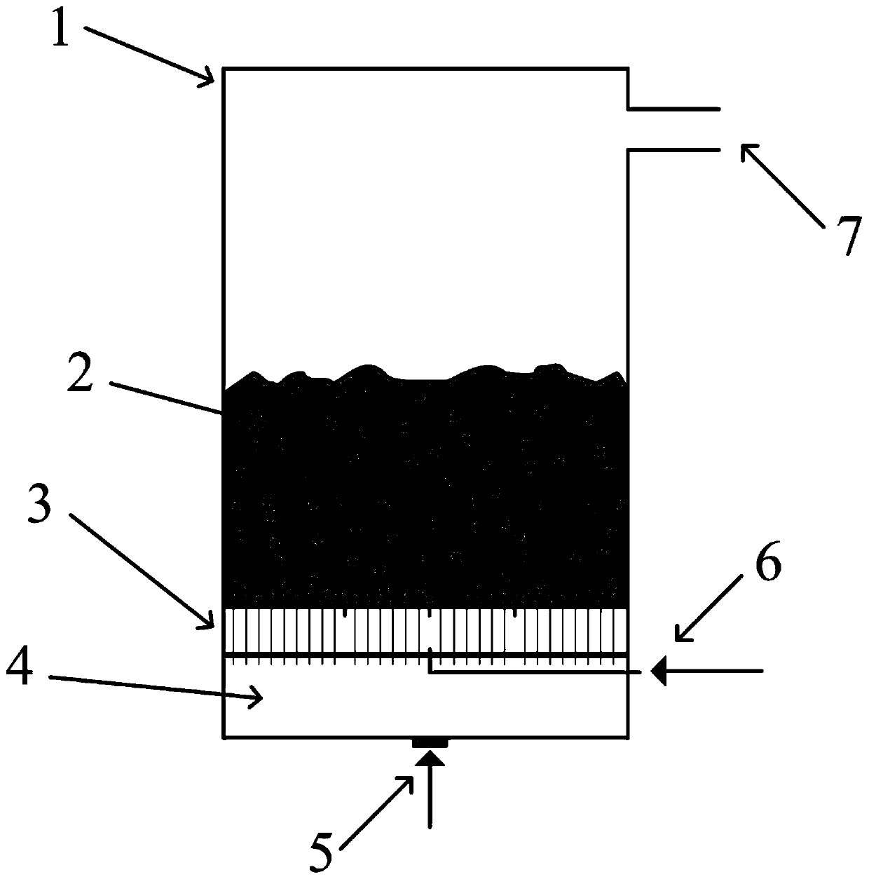
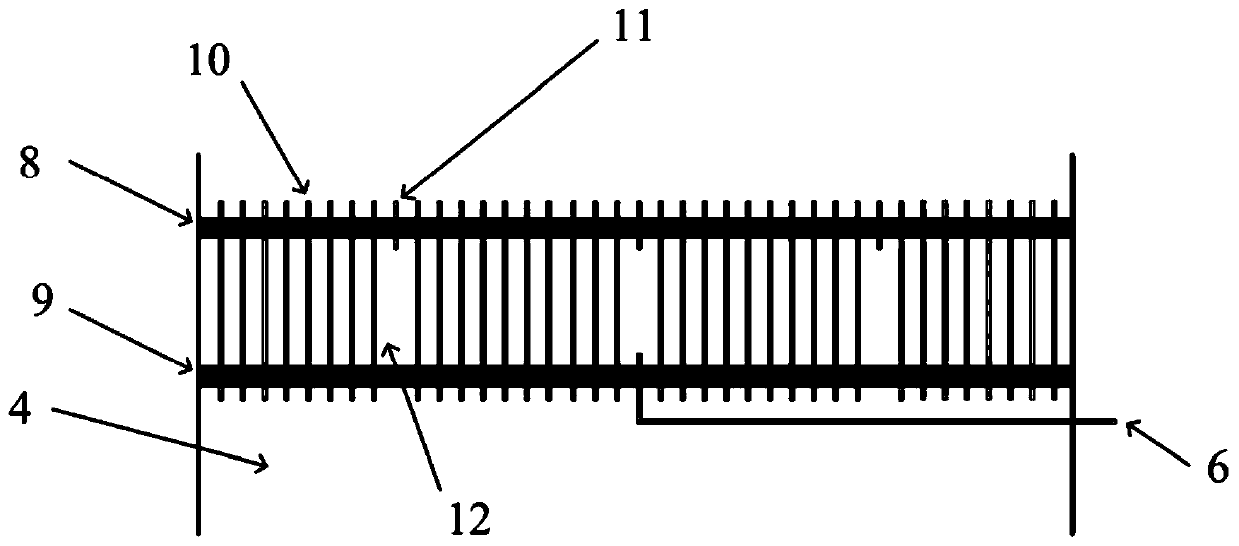
The invention relates to the technical field of combustion devices for ammonia gas, and provides a fluidized bed combustion device for ammonia gas, a power generation system and a combustion method ofthe ammonia gas. The combustion device comprises fluidized bed combustor shell, a fluidized bed layer, an air distributing plate, a pumping chamber, a combustion-supporting gas inlet, a fuel gas inlet pipe and a flue gas exhaust port; the air distributing plate is wholly mounted at the lower part of the fluidized bed combustor shell, and the fluidized bed layer is arranged on the upper surface ofthe air distributing plate; the pumping chamber is located below the air distributing plate; the combustion-supporting gas inlet is formed in the pumping chamber; the fuel gas inlet pipe is fixed onthe air distributing plate and communicates with an inner cavity of the air distributing plate; and the flue gas exhaust port is formed in the upper part of the fluidized bed combustor shell. According to the designed fluidized bed combustion device, the problems of has high firing energy, high flame propagation velocity, narrow firing concentration range and unstability of ammonia gas combustionare solved thoroughly. Therefore, the power generation system can successfully use the ammonia gas as fuel, and the remarkable carbon dioxide emission reducing effect is realized.

Description

technical field [0001] The invention relates to the technical field of ammonia combustion devices, in particular to an ammonia fluidized bed combustion device, a power generation system based on the device and a combustion method based on the power generation system. Background technique [0002] The information disclosed in the Background of the Invention is only intended to increase the understanding of the general background of the invention, and is not necessarily to be taken as an acknowledgment or any form of suggestion that the information constitutes the prior art that is already known to those skilled in the art. [0003] Since the industrial revolution, the combustion of a large amount of fossil fuels such as coal, oil, and natural gas has led to an increase in the concentration of carbon dioxide in the atmosphere, resulting in global climate change, bringing about many problems such as melting cold glaciers, rising sea levels, and frequent forest fires in tropical ...

Claims


Application Information

Patent Timeline
Patent Type & Authority Applications(China)
IPC IPC(8): F23C10/16F23C10/18F23C10/20F22B31/00F02C6/00F01D15/10
CPCF01D15/10F02C6/00F22B31/0007F23C10/16F23C10/18F23C10/20
Inventor 张东柯张柘子高健朱明明武俊智徐文强
Owner QINGDAO INST OF BIOENERGY & BIOPROCESS TECH CHINESE ACADEMY OF SCI
Learn More