
Electric heating plate

A technology of electric heating and heating plate, applied in the direction of heating element shape, etc., can solve the problems of easy desoldering of conductive electrode coating and conductive terminal, low energy conversion efficiency, and low energy efficiency of electric ceramic furnace, so as to avoid poor contact , Good heat conduction effect, good conduction effect of electric energy

Pending Publication Date: 2020-06-26
中山市特美新电子商务有限公司
View PDF0 Cites 1 Cited by
  • Summary
  • Abstract
  • Description
  • Claims
  • Application Information

AI Technical Summary

Problems solved by technology

[0004] However, the nickel-chromium heating sheet of the heating element of the existing electric ceramic furnace is embedded on the insulating and heat-insulating plate. During the heating process, the insulating and heat-insulating plate absorbs heat to generate heat loss, and there is a If there is a certain gap, the heat of the nickel-chromium heating sheet will be transferred to the microcrystalline plate, and a certain heat loss will be generated, resulting in a decrease in thermal efficiency, and the energy conversion efficiency of the existing heating elements such as the nickel-chromium heating sheet is not high. Electric ceramic hobs are not energy efficient
[0005] In addition, graphene heat-generating coatings have been coated on fiber cloth, heat-conducting plates and other objects, which are mainly used in occasions where the heating temperature is not high. The conductive electrode coating and the conductive terminals are generally connected by soldering. When heating generates high temperature, the conductive electrode coating and the conductive terminal are easily desoldered

Method used


Image

  • Electric heating plate
  • Electric heating plate
  • Electric heating plate

Examples


Embodiment

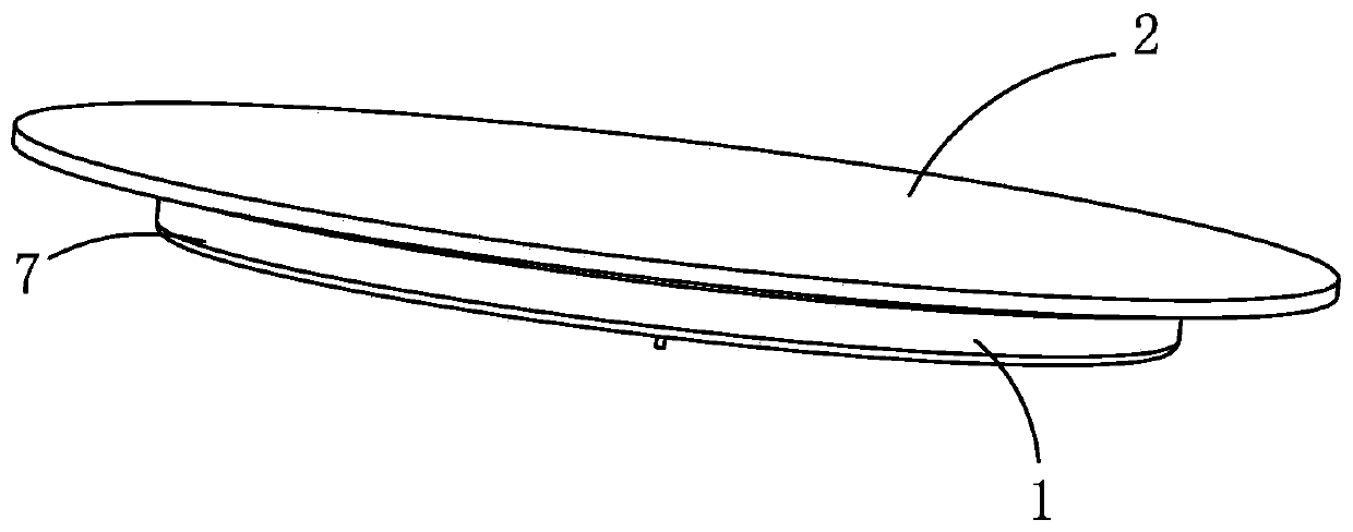
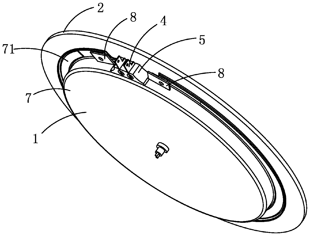
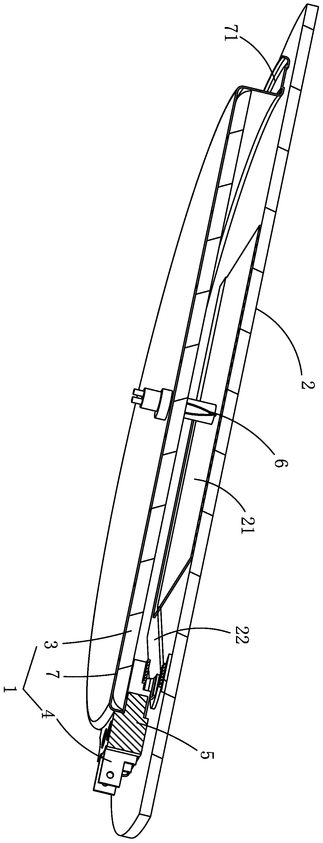
[0036] Example, combined with Figure 1 to Figure 11 As shown, an electric heating plate includes a furnace body 1, a high-temperature heat conduction plate 2, a mounting seat 5, a thermocouple 6 and a controller.

[0037] The furnace body 1 includes a heating disc shell 7, a heat insulating layer 3, and an elastic conductive sheet 4. The upper part of the furnace body 1 is open, and the heat insulating insulating layer 3 is arranged in the heating disc shell 7, and the side wall of the heating disc shell 7 is provided with The gap 11, the mounting base 5 is a ceramic insulating base, the mounting base 5 is fixed on the gap 11, the mounting base 5 has a slot 51, and the bottom of the slot 51 has a socket 52.

[0038] The heating disc shell 7 is provided with a flange 71, and the heating disc shell 7 is bonded to the bottom surface of the high-temperature heat conducting plate 2 through high-temperature silicone glue.

[0039] The high-temperature heat-conducting plate 2 is a ...


PUM


Abstract

The invention relates to an electric heating plate. The electric heating plate comprises a high-temperature heat-conducting plate and a furnace body, wherein the bottom surface of the high-temperatureheat conduction plate is coated with a graphene heating coating; the bottom surface of the graphene heating coating is coated with a conductive electrode coating; the graphene heating coating is electrically connected with the conductive electrode coating; the furnace body comprises a heating disc shell, a heat insulation layer and an elastic conductive sheet, wherein the heat insulation layer isarranged in the heating disc shell, the elastic conductive sheet is arranged on the heating disc shell, and the elastic conductive sheet is in close contact with the corresponding conductive electrode coating. The graphene heating coating is directly coated on the bottom surface of the high-temperature heat conduction plate, so the heat of the graphene heating coating is directly transferred to the high-temperature heat conduction plate, the heat transfer effect is improved, the conductive electrode coating is directly coated on the graphene heating coating, the conductive electrode coating and the graphene heating coating are tightly combined, and the electric energy conduction effect is good.

Description

technical field [0001] The invention relates to an electric heating disc. Background technique [0002] The existing electric ceramic furnace is mainly composed of a heating plate, a microcrystalline plate, an electric control system, a temperature control system and an electric ceramic furnace shell. The nickel-chromium heating sheet is embedded on the insulating heat-insulating plate and placed in the shell of the heating plate. One end of the conductive terminal is connected to the input end of the nickel-chromium heating plate in a clamping manner, and the other end of the conductive terminal is connected to the electric control system through a wire. connect. [0003] The existing electric ceramic furnace uses the principle of infrared heating technology. After the nickel-chromium heating sheet is energized, it generates heat and emits infrared rays to generate heat, which realizes uniform heating, and can carry out continuous heating, and hardly generates electromagne...

Claims


Application Information

Patent Timeline
Patent Type & Authority Applications(China)
IPC IPC(8): H05B3/46
CPCH05B3/46
Inventor 张维刚
Owner 中山市特美新电子商务有限公司
Learn More