Tap water treatment device
A treatment device, tap water technology, applied in water/sewage treatment, water/sewage multi-stage treatment, water/sludge/sewage treatment, etc., can solve the problems of complex filtration function, unsuitable for purification production, low filtration efficiency, etc.
Inactive Publication Date: 2020-07-03
杨玉梅
7 Cites 0 Cited by
AI-Extracted Technical Summary
Problems solved by technology
[0005] In order to overcome the shortcomings in the prior art that the filtration function is too complicated, the cost is high, the filtration efficiency is low, it is not suitable...
Method used
Double circle stacking wheel 506 is set to the vertical dislocation superposition of two groups of discs; Disturbance frame 507 is set to stack after two limit frames rotate ninety degrees, utilizes the rotation of two groups of discs, drives disturbance frame 507 to carry out Irregular cyclic swings make the slightly soluble matter spread into the tap water, and then use the impact of water to disperse them, increasing the diffusion speed of crystal nuclei.
During use, by the rotation of the 8th transmission wheel 702, drive the 4th bevel gear 703 to rotate, and then the transmission crank 704 rotates, then will be driven by the first limiter 705 and the 3rd limiter 7010 respectively The asynchronous lifting of the seventh transmission rod 706 and the ninth transmission rod 7011 makes the advection sedimentation cabin 707 swing quickly left and right, and makes the water in the cabin form microwaves, and then use the microwaves to settle, which speeds up the settling speed and changes The original natural settlement method is adopted, and at the same time, the silt is used to push the plate 7014 to move to the right, and the upper slide rail of the third limiting rail 7013 is passed, so that the silt deposited on the bottom of the bilge will not appear during the sliding, and then The silt pushing plate 7014 slides to the left from the lower layer of the third limiting rail 7013, and the silt at the bilge is cleared out, so that the silt at the bilge can be removed in a timely and effective manner. Stir to prevent the tap water in the cabin from being polluted again after it appears.
Principle of work: when using tap water treatment device, installation bracket 1 is fixed on the level ground between factories, then starts by control terminal 3, and servo motor 2 rotates, and then utilizes the first drive wheel 4 transmission wave advection mechanisms 7. Drive the alum flower generating mechanism 5 again, and then inject the raw water to be treate...
Abstract
The invention relates to a water purification technology, in particular to a tap water treatment device. The technical problem to be solved by the invention is to provide the tap water treatment device. The tap water treatment device comprises a mounting bracket, a servo motor, a control terminal, a first transmission wheel, an alumen ustum forming mechanism, an air flow recoil mechanism and a swing wave advection mechanism, the right part of the inner bottom end of the mounting bracket is in bolted connection with the servo motor, the right part of the top end of the mounting bracket is welded with the alumen ustum forming mechanism, the air flow recoil mechanism is arranged at the left bottom in the mounting bracket, and the left portion of the top end of the mounting bracket is providedwith the swing wave advection mechanism. According to the invention, active impact is carried out by flapping water, the flocculation effect is accelerated, then flocculation crystal nucleuses are provided by using slightly soluble substances, alumen uvium floc is formed, micro-vibration is carried out, flocculate is rapidly settled, sludge is formed at the bottom of a cabin, adhesion accumulation of microorganisms and adhesion of flocculate are reduced, and a filtering stone is repeatedly utilized.
Application Domain
Treatment involving filtrationMultistage water/sewage treatment +2
Technology Topic
Water treatmentMechanical engineering +6
Image
Examples
- Experimental program(1)
Example Embodiment
[0028] Example
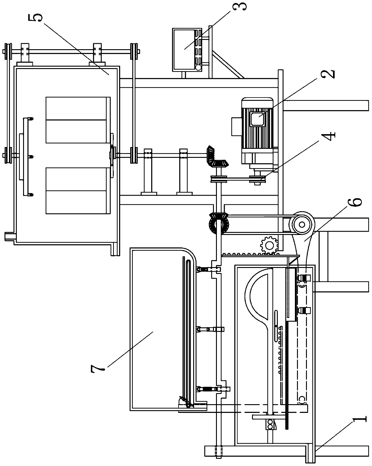
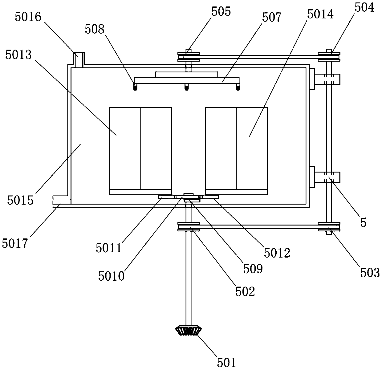
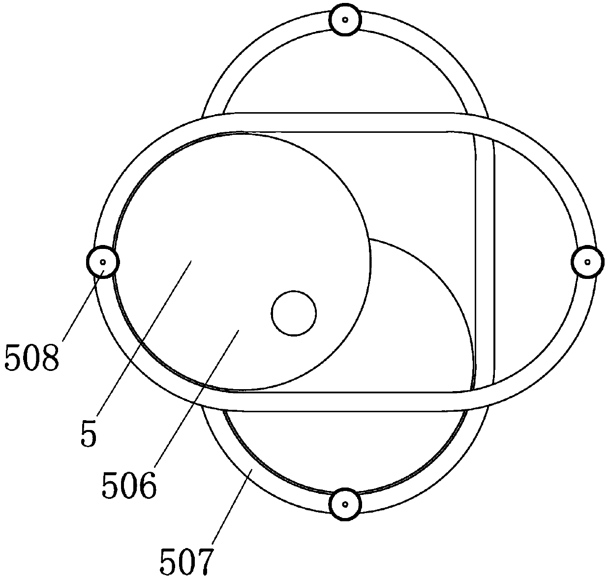
[0029] A tap water treatment device, such as Figure 1-7 As shown, it includes the mounting bracket 1, the servo motor 2, the control terminal 3, the first transmission wheel 4, the alum generating mechanism 5, the air-water flow recoil mechanism 6 and the wave advection mechanism 7; the inner bottom right part of the mounting bracket 1 and Servo motor 2 is bolted; the middle of the right end of the mounting bracket 1 is welded to the control terminal 3; the top right of the mounting bracket 1 is welded to the alum generating mechanism 5; the left bottom of the mounting bracket 1 is provided with an air-water flow recoil mechanism 6; installation The top left part of the bracket 1 is provided with a wave advection mechanism 7, and the rear right bottom of the wave advection mechanism 7 is connected with the alum generating mechanism 5, and the top right end of the wave advection mechanism 7 is connected with the air-water flow recoil mechanism 6; The middle of the left end of the servo motor 2 is plugged into the first transmission wheel 4, and the top of the first transmission wheel 4 is connected to the wave-advection mechanism 7 through a belt.
[0030] Working principle: When using a tap water treatment device, fix the mounting bracket 1 on the level ground in the factory, and then start it through the control terminal 3, the servo motor 2 rotates, and then the first transmission wheel 4 is used to drive the oscillating advection mechanism 7, and then Drive the alum generating mechanism 5, and then inject the raw water to be treated into the alum generating mechanism 5, and sprinkle the flocculant and the slightly soluble matter of smaller particles into the alum generating mechanism 5. The water is actively impacted to accelerate the flocculation effect, and then use the slightly soluble matter to provide the flocculation nucleus to form alum. Then, the treated water is discharged into the oscillating-advection mechanism 7, and the oscillating-advection mechanism 7 is allowed to stand still. The micro-vibration of the oscillating advection mechanism 7 is used to make the flocs settle quickly, and then the silt is formed in the bilge, and then the water is discharged. After the completion, the sludge is removed, and the air-water flow recoil mechanism 6 is used to process the sedimentation. Then the filter stone is filtered to remove microorganisms and undissolved flocs, and then the filter stone is intensively turned and cleaned by air and water flow, so that the filter stone is reused, reducing the adhesion of microorganisms and the adhesion of flocs, and achieves the goal The moving water carries out active impact to accelerate the flocculation effect, and then uses the micro-soluble matter to provide the flocculation nucleus to form alum, and then uses the micro-vibration vibration to make the flocs settle quickly, and then the silt is formed at the bottom of the bilge. Concentrated turning and cleaning enables repeated use of the filter stone, reducing the adhesion and accumulation of microorganisms and the effect of adhesion of flocs.
[0031] The alum generating mechanism 5 includes a first bevel gear 501, a second transmission wheel 502, a third transmission wheel 503, a fourth transmission wheel 504, a fifth transmission wheel 505, a double circular stack wheel 506, a disturbance frame 507, and a slightly molten Head 508, first shift lever 509, second transmission lever 5010, third transmission lever 5011, fourth transmission lever 5012, first water flow collision fan 5013, second water flow collision fan 5014, meltdown chamber 5015, water injection port 5016 and the first water outlet 5017; the top middle of the first bevel gear 501 is inserted into the second transmission wheel 502 through a round rod; the right end of the second transmission wheel 502 is connected to the third transmission wheel 503 through a belt; the second transmission wheel The middle of the top of 502 is plugged with the first shift rod 509; the middle of the top of the third transmission wheel 503 is plugged with the fourth transmission wheel 504 through a round rod; the left end of the fourth transmission wheel 504 is connected with the fifth transmission wheel 505 through a belt. ; The middle of the bottom end of the fifth transmission wheel 505 is inserted into the double circle stack wheel 506; the outer surface of the double circle stack wheel 506 is in transmission connection with the disturbance frame 507; the bottom dead corner of the disturbance frame 507 is connected with the micro-melt sprinkler 508; The top end of the first shift rod 509 is in transmission connection with the second transmission rod 5010; the bottom end of the first shift rod 509 is rotationally connected with the descent chamber 5015 through a round rod; the rear left part of the second transmission rod 5010 is connected to the third transmission rod 5011 Transmission connection; the rear right part of the second transmission rod 5010 and the fourth transmission rod 5012 for transmission connection; the rear end of the third transmission rod 5011 and the first water flow collision fan 5013 for transmission connection; the fourth transmission rod 5012 behind the top end The left part of the dissolving chamber 5015 is connected to the water injection port 5016; the bottom of the left end of the dissolving chamber 5015 is connected to the first water outlet 5017; the bottom of the first bevel gear 501 The rear part of the end is connected with the air-water flow recoil mechanism 6; the bottom end of the dissolution chamber 5015 is connected with the mounting bracket 1.
[0032] When using the alum generating mechanism 5, the second transmission wheel 502 is driven to rotate through the rotation of the first bevel gear 501, and then the third transmission wheel 503 is used to drive the rotation of the fourth transmission wheel 504, and then the fifth transmission wheel 505 is used for rotation. Rotate, the fifth transmission wheel 505 drives the rotation of the double circular stack wheel 506, which drives the disturbance frame 507 to sway, and the micro-melt sprinkler 508 is used to sprinkle the micro-melt into the melting chamber 5015, while the second transmission wheel 502 drives The first lever 509 rotates, and then the second transmission rod 5010 is waved, and then the first water flow collision fan 5013 and the second water flow collision fan 5014 are driven to reverse by the third transmission rod 5011 and the fourth transmission rod 5012, respectively Rotating, and then driving the liquid in the dissolution chamber 5015 to actively reverse flow, which improves the formation of alum with the slightly soluble matter as the nucleus and then the flocculant, which helps the subsequent flocculation and settlement.
[0033] The air-water flow recoil mechanism 6 includes a second bevel gear 601, a sixth transmission wheel 602, a seventh transmission wheel 603, a fifth transmission rod 604, a sixth transmission rod 605, a moving rod 606, a filter stone push plate 607, and a first limiter. Position rail 608, wash cabin 609, first gear rod 6010, position adjustment lever 6011, first straight gear 6012, second gear rod 6013, lifting plate 6014, filter 6015, first air and water flow gun 6016, first Two air water jets 6017 and a second water outlet 6018; the middle of the rear end of the second bevel gear 601 is inserted into the sixth transmission wheel 602; the bottom end of the sixth transmission wheel 602 is connected to the seventh transmission wheel 603 through a belt; The middle of the rear end of the seventh transmission wheel 603 is inserted into the fifth transmission rod 604; the left end of the seventh transmission wheel 603 is provided with a first spur gear 6012; the left end of the fifth transmission rod 604 is in transmission connection with the sixth transmission rod 605; The left end of the sixth transmission rod 605 is in transmission connection with the push rod 606; the bottom and middle part of the front end of the push rod 606 is bolted to the filter stone push plate 607; the left part of the rear end of the filter stone push plate 607 is slidingly connected to the first limit rail 608; The rear end of the first limit rail 608 is welded to the washing cabin 609; the bottom middle of the right end of the push rod 606 is welded to the first rack 6010; the bottom right middle of the first limit rail 608 is provided with an adjustment lever 6011, and The middle part of the rear end of the adjustment lever 6011 is connected with the washing cabin 609; the left end of the first spur gear 6012 meshes with the second gear rod 6013; the bottom left end of the second gear rod 6013 is welded with the lifting plate 6014; inside the washing cabin 609 The middle part is welded to the filter screen 6015; the bottom right part of the filter screen 6015 is provided with a first air-water flow gun 6016; the bottom right part of the filter screen 6015 is provided with a second air-water flow gun 6017 and a second air-water flow gun 6017 Located on the left side of the first air water jet gun 6016; the left end of the washing chamber 609 is connected with the second water outlet 6018; the front right part of the second bevel gear 601 is connected with the wave advection mechanism 7; the bottom end of the washing chamber 609 Connect with mounting bracket 1.
[0034] When in use, the sixth transmission wheel 602 is driven to rotate through the rotation of the second bevel gear 601, and then the seventh transmission wheel 603 is driven to rotate through the belt, and then the fifth transmission rod 604 is transmitted, and then the sixth transmission rod 605 is transmitted. Swing, and then drive the push rod 606 to swing left and right, and then slide the filter stone push plate 607 to the left in the first limit rail 608, and then press the left end of the filter stone push plate 607 to contact the adjustment lever 6011 to press down. The right end is tilted to guide the filter stone push plate 607 into the upper part of the first limit rail 608, and at the same time push the filter stone into the lifting plate 6014 on the right side of the filter 6015, and then drive the first gear rod 6010 through the push rod 606 Move to the right, engage the first spur gear 6012 to rotate, and then lower the lifting plate 6014 by engaging the second gear rod 6013, and then use the first air-water flow gun 6016 and the second air-water flow gun 6017 to entrain air on the filter stone The water flow is cleaned to remove the accumulation of microorganisms and the adhesion of flocs on the surface, and then reuse the filter stone, and then move it to the left by pushing, and then engage the first straight gear 6012 to drive the second gear rod 6013 to lift the plate 6014 Lift up and at the same time pull the filter stone push plate 607 to the left to re-lay the filter stone on the filter screen 6015, and then pass the treated tap water from the second outlet 6018.
[0035] The wave advection mechanism 7 includes a third bevel gear 701, an eighth transmission wheel 702, a fourth bevel gear 703, a curved rod 704, a first stopper 705, a seventh transmission rod 706, an advection sedimentation chamber 707, and a second stop 708, eighth transmission rod 709, third limiter 7010, ninth transmission rod 7011, second limit rail 7012, third limit rail 7013, silt pushing plate 7014 and third water outlet 7015; third cone The middle left end of the gear 701 is inserted into the eighth transmission wheel 702; the middle left end of the third bevel gear 701 is inserted into the fourth bevel gear 703 through a round rod; the middle left end of the fourth bevel gear 703 is inserted into the curved rod 704; The right part of the outer surface of the rod 704 is rotatably connected with the first stopper 705; the middle part of the outer surface of the curved rod 704 is rotatably connected with the second stopper 708; the left part of the outer surface of the curved rod 704 rotates with the third stopper 7010 Connection; the top end of the first stopper 705 is in transmission connection with the seventh transmission rod 706; the top end of the seventh transmission rod 706 is in transmission connection with the advection sedimentation chamber 707; the inner bottom of the advection sedimentation chamber 707 is welded to the second limit rail 7012; The inner bottom of the advection sedimentation tank 707 is connected to the third limit rail 7013 in transmission; the left part of the bottom end of the advection sedimentation tank 707 is connected to the third water outlet 7015; the top end of the second limiter 708 is welded to the eighth transmission rod 709 , And the top end of the eighth transmission rod 709 is connected with the advection sedimentation chamber 707; the top end of the third stopper 7010 is in transmission connection with the ninth transmission rod 7011, and the top end of the ninth transmission rod 7011 is connected with the advection sedimentation chamber 707; second The inner left part of the limit rail 7012 is slidably connected with the sludge pushing plate 7014, and the bottom of the front end of the sludge pushing plate 7014 is connected with the third limit rail 7013; the top of the right end of the third bevel gear 701 is connected with the first bevel gear 501; The bottom end of the eight transmission wheel 702 is connected with the first transmission wheel 4 through a belt; the rear left end of the fourth bevel gear 703 is connected with the second bevel gear 601; the bottom end of the advection sedimentation chamber 707 is connected with the mounting bracket 1.
[0036] In use, the rotation of the eighth transmission wheel 702 drives the fourth bevel gear 703 to rotate, and then drives the crank 704 to rotate, and then drives the seventh transmission through the first stopper 705 and the third stopper 7010 respectively The asynchronous lifting of the rod 706 and the ninth transmission rod 7011 causes the advection sedimentation chamber 707 to swing quickly from side to side, and causes the water in the chamber to form microwaves, and then uses the microwaves to settle, which accelerates the settlement speed and changes the original At the same time, the silt pushing plate 7014 is used to move to the right, passing through the upper slide rail of the third limit rail 7013, and the silt deposited on the bottom of the bilge will not appear during sliding, and then the silt pushing the plate The 7014 slides to the left from the lower layer of the third limit rail 7013 to clear the silt in the bilge, so that the silt in the bilge can be removed in time and effectively. At the same time, the silt pushing plate 7014 will not agitate the settled silt to prevent The tap water in the tank was polluted again after it emerged.
[0037] The double-circle stacking wheel 506 is set to superimpose the longitudinal displacement of the two sets of discs; the disturbance frame 507 is set to superimpose the two limit frames after rotating 90 degrees. The rotation of the two sets of discs drives the disturbance frame 507 to perform irregular Cycling oscillating, so that the slightly soluble matter is scattered into the tap water, and then dispersed by the impact of the water flow, which improves the diffusion speed of the crystal nucleus.
[0038] The tops of the first water flow collision fan 5013 and the second water flow collision fan 5014 are both equipped with a horseshoe-shaped structure. The arc-shaped fan blades are used to push the water away, and then the flat fan blades are used to deliver water. The vortex is used for backflushing and mixing for the first time to improve efficiency.
[0039] The protrusion on the left part of the bottom end of the filter stone push plate 607 is set in an arc-shaped structure, and the position adjustment lever 6011 can be smoothly pressed down during the process of moving to the left, so that it will not stop at the stuck position.
PUM


Description & Claims & Application Information
We can also present the details of the Description, Claims and Application information to help users get a comprehensive understanding of the technical details of the patent, such as background art, summary of invention, brief description of drawings, description of embodiments, and other original content. On the other hand, users can also determine the specific scope of protection of the technology through the list of claims; as well as understand the changes in the life cycle of the technology with the presentation of the patent timeline. Login to view more.