Hollow slab bridge bending and shearing mixed reinforcing method

A hollow, bending and shearing technology, applied in bridge reinforcement, bridge, bridge maintenance, etc., can solve the problems of reducing the clearance under the bridge, single reinforcement effect, cumbersome operation, etc., and achieve high construction efficiency, comprehensive reinforcement effect and good integrity Effect

Pending Publication Date: 2020-07-03
NANJING FORESTRY UNIV
View PDF3 Cites 1 Cited by
  • Summary
  • Abstract
  • Description
  • Claims
  • Application Information

AI Technical Summary

Problems solved by technology

This structure improves the flexural bearing capacity of the old bridge, but the improvement of the shear bearing capacity is very limited. At the same time, the cost of the carbon fiber plate is relatively high. At the same time, the pouring of the modified polymer concrete requires a formwork, which is cumbersome to operate; another example is the Chinese patent "201720336408.5 "Discloses a transversely reinforced hollow slab bridge, including bridge deck girders, reinforced beams and transversely reinforced plates, steel pipes running through the hollow slab girders are connected in opposite tension between the reinforced beams and the transversely reinforced plates, and the structure is reinforced by transverse steel beams It can avoid the stress on the single plate, and the integrity of the beam body is good. However, the bending and shear reinforcement effects of the bridge are average, and the transverse reinforcement plate needs to be removed from the bridge deck pavement, interrupting traffic, and time-consuming; another example is the Chinese patent "2018209916...

Method used


Image

  • Hollow slab bridge bending and shearing mixed reinforcing method
  • Hollow slab bridge bending and shearing mixed reinforcing method
  • Hollow slab bridge bending and shearing mixed reinforcing method

Examples


Embodiment Construction

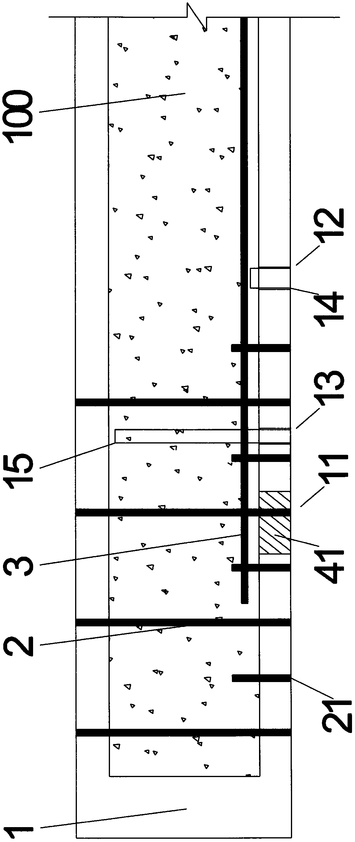
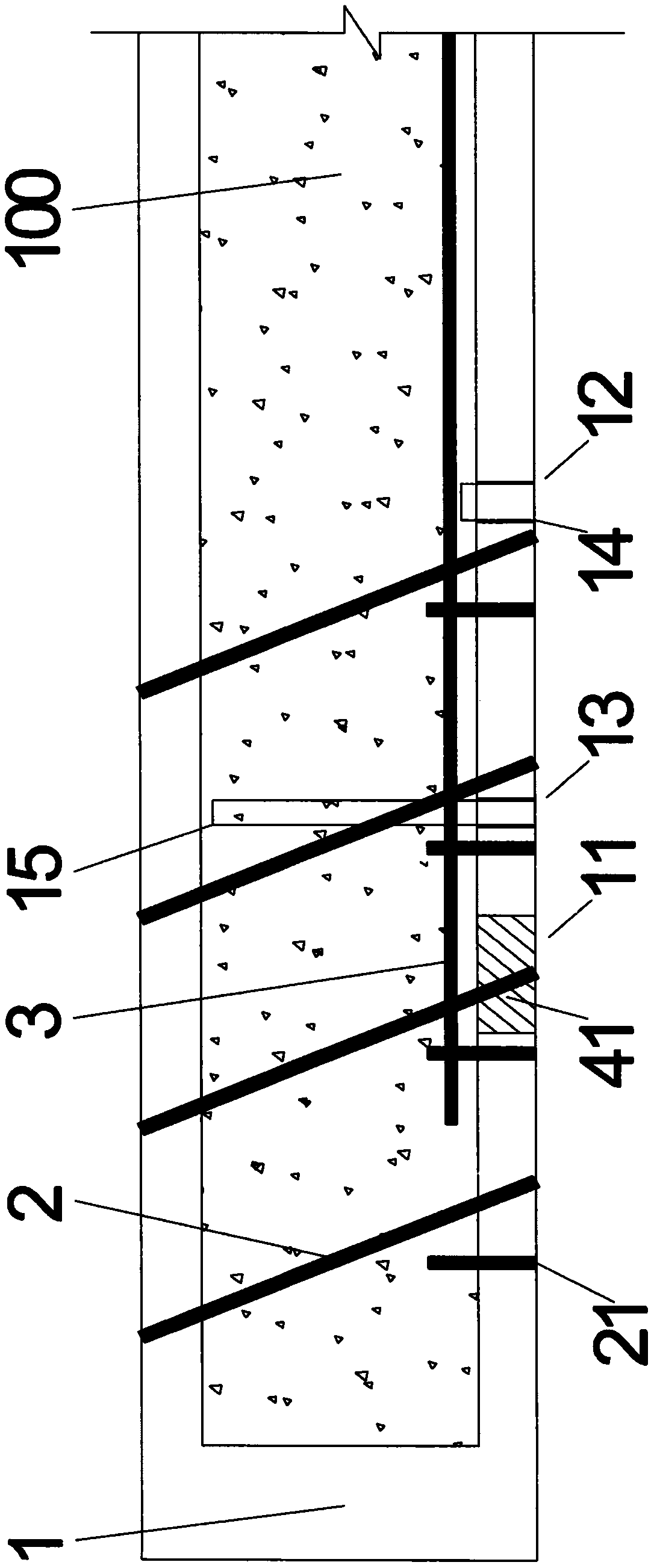
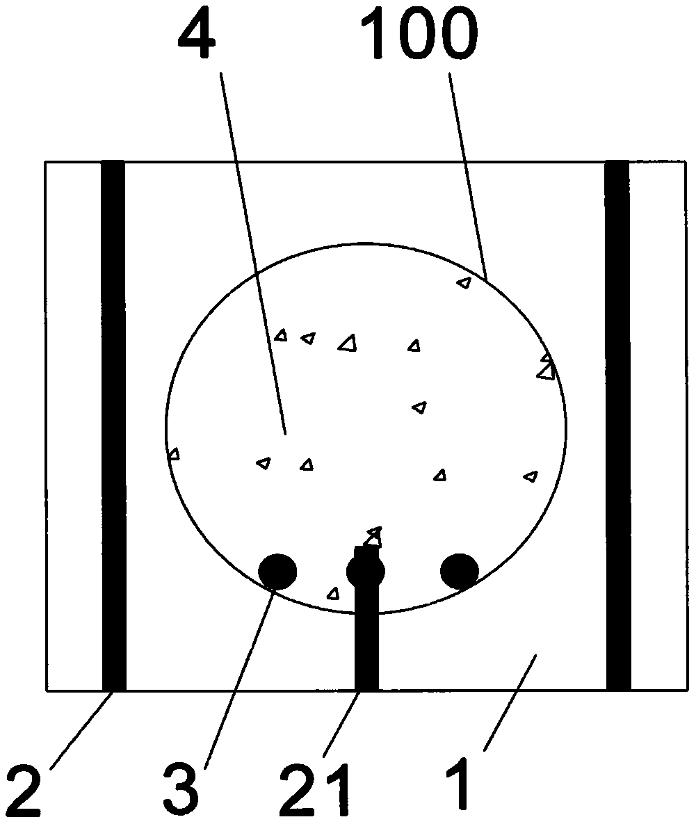
[0044] The present invention will be further described below in conjunction with the accompanying drawings. As shown in the accompanying drawings, a hollow-core slab bridge bending and shearing hybrid reinforcement method is characterized in that the bottom of the hollow-core slab bridge 1 is provided with a working channel 11, a perfusion hole 12 and an outlet The air hole 13 is connected to the cavity 100 of the hollow slab bridge 1, and the longitudinal steel bars 3 are arranged in the cavity 100 of the hollow slab bridge 1 along the axis direction of the hollow slab bridge 1 through the working tunnel 11, and the working hole is blocked with a plug 41 11. The filler 4 is filled into the cavity 100 of the hollow slab bridge 1 through the pouring hole 12. After the filler 4 is finally set, drill holes vertically or outwardly from the bottom up, and implant more than one row of shear steel bars 2 and fill it A number of connecting keys 21 are arranged between the object 4 and t...


PUM

PropertyMeasurementUnit
Lengthaaaaaaaaaa

Abstract

A hollow slab bridge bending and shearing mixed reinforcing method comprises the following steps: arranging longitudinal steel bars in a cavity of a hollow slab bridge, pouring a filler into the cavity, drilling holes in the bottom of the hollow slab bridge from bottom to top, and implanting one or more rows of shearing-resistant steel bars to finish the bending and shearing mixed reinforcement ofthe hollow slab bridge. The filler is connected with the existing beam body into a whole through the shear-resistant steel bars and connecting keys, the longitudinal steel bars and the filler act together to realize the anti-bending reinforcement of the hollow slab bridge, and the shear-resistant steel bars and the filler act together to realize the shear-resistant reinforcement of the hollow slab bridge. The method can be achieved under the condition that traffic is not affected, the structure is simple and easy to understand, the construction efficiency is high, the appearance of an existing bridge is not changed, the bending resistance and shear capacity of the hollow slab bridge are improved at the same time, and the improvement effect is remarkable.

Description

Technical field [0001] The invention belongs to the field of civil engineering, and relates to a method for strengthening bridges, in particular to a method for bending and shearing mixed strengthening of hollow slab bridges. Background technique [0002] Hollow slab bridges are widely used in small and medium span bridges due to their simple structure, convenient transportation and construction, light weight and high prefabrication. It can be said that hollow slab bridges are one of the most common bridge structures in my country. With the development of traffic, the traffic volume is increasing, and the load value on the bridge structure is also greatly increased. The increase in load causes insufficient flexural capacity and shear capacity. Bridges with insufficient capacity are directly demolished and reconstructed. , It is not only a waste of resources, but also needs to interrupt traffic, high cost and long construction period. Therefore, reinforcement methods are usually u...

Claims


Application Information

Patent Timeline
IPC IPC(8): E01D22/00
CPCE01D22/00
Inventor 魏洋朱超柴继乐程勋煜董峰辉李国芬
Owner NANJING FORESTRY UNIV
Why Eureka
Try Eureka