BOOST power conversion circuit and control method thereof

A technology for converting circuits and power, which is applied in the field of photovoltaic grid-connected inverter BOOST step-up power conversion circuit and its control, which can solve the problems of overvoltage breakdown of the second switching tube, overvoltage breakdown of diodes, and affecting circuit efficiency, etc.

Pending Publication Date: 2020-07-03
NINGBO GINLONG TECH
View PDF0 Cites 1 Cited by
  • Summary
  • Abstract
  • Description
  • Claims
  • Application Information

AI Technical Summary

Problems solved by technology

[0004] 1. When the power is initially turned on and the input voltage is high, since the initial voltage of the flying capacitor is equal to zero at this time, the input voltage will be fully applied to the second switch tube T2, which will cause overvoltage breakdown of the switch tube T2 in severe cases
For example: Since the front stage of the photovoltaic grid-connected inverter is generally multi-channel MPPT parallel connection (such as Figure 13 ), when the input voltage of one of the MPPTs reaches the initial start-up voltage V of the MPPT start At this time, assuming that the initial voltage of the flying capacitor is equal to zero, the voltage on both ends of the second switching tube T2 is equal to V in , in extreme cases, V in =1500V, it will cause instantaneous overvoltage breakdown of the second switching tube
[0005] 2. When the bus voltage is established and a certain MPPT is not started, since the initial voltage of the flying capacitor voltage is equal to zero, the output bus voltage will be fully applied to the fourth diode D4, which will cause overvoltage breakdown of the diode in severe cases
At this time, it is necessary to choose a diode with a high withstand voltage value, and a diode with a high withstand voltage value has a high tube voltage drop and poor reverse recovery characteristics, which will seriously affect the circuit efficiency when used.
[0006] The above two potential problems will bring serious challenges to the device design of the circuit, so appropriate measures must be taken to obtain a method to ensure the safety of the second switch tube and reduce the voltage stress of the fourth diode to ensure the circuit efficiency, lower system cost

Method used


Image

  • BOOST power conversion circuit and control method thereof
  • BOOST power conversion circuit and control method thereof
  • BOOST power conversion circuit and control method thereof

Examples


Embodiment Construction

[0028] In order to make those skilled in the art better understand the technical solutions provided by the embodiments of the present application, the working principle of the existing three-level Boost circuit is described below as an example.

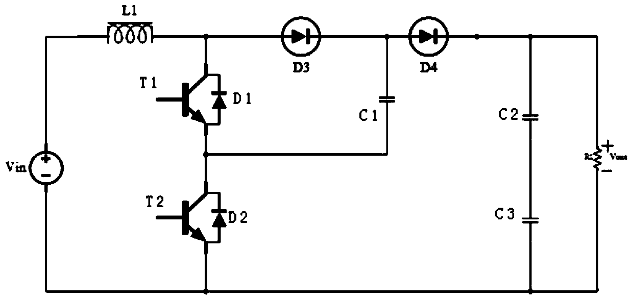
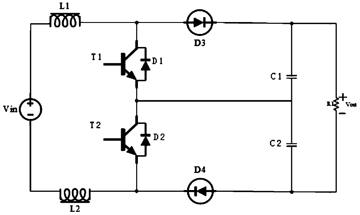
[0029] like Figure 1-a As shown, resistor R1 is the load unit, C3 and C4 are the bus capacitors on the output side of the Boost circuit, according to the input voltage V in and the output voltage V out The relationship between the Boost circuit and the duty cycle D 0.5 two operating modes respectively:

[0030] 1. When V in >0.5V out When the duty cycle D < 0.5;

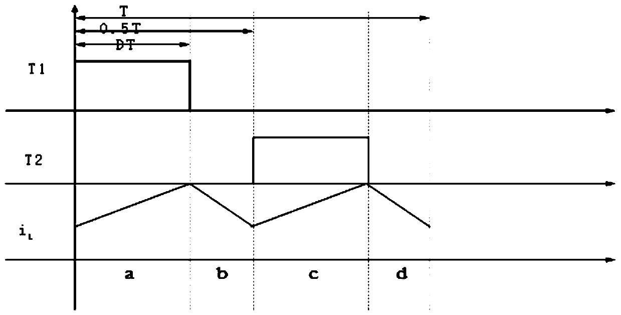
[0031] In this working mode, the waveform of the driving signal is as follows figure 2 As shown, the current flow paths in each switching mode are as follows Figure 3-6As shown, the realization represents the current flow path, and C2 and C3 are the bus capacitors. In the figure, T is the switching period, and the driving signals of T1 and T2 differ by a phase angl...


PUM


Abstract

The invention discloses a BOOST power conversion circuit and a control method thereof. According to the conversion circuit, an initial voltage establishing circuit of a flying capacitor C1 is added onthe basis of an input and output common-ground type three-level Boost converter. The initial voltage establishing circuit is composed of a first resistor R1, a second resistor R2 and a third resistorR3. Initial voltage is established for a first capacitor C1 when the voltage of the input end of the voltage-boosting power conversion circuit is lower than starting threshold voltage Vstart of the voltage-boosting power conversion circuit, and the BOOST power conversion circuit has the effects that firstly, forward voltage of a second switching tube T2 is reduced; and secondly, the reverse voltage borne by the fourth diode D4 is reduced, the second switching tube T2 is further protected, and the fourth diode D4 with smaller reverse voltage stress can be selected.

Description

technical field [0001] The invention relates to the technical field of power electronics, in particular to a photovoltaic grid-connected inverter BOOST boost power conversion circuit and a control method thereof applied to a multi-channel MPPT. Background technique [0002] The boost circuit is a boost power conversion circuit, which can boost the input voltage and output it, thereby realizing power conversion. Usually the Boost circuit includes a two-level Boost circuit and a multi-level Boost circuit. The two-level Boost circuit is generally used in applications with lower voltage levels, and the multi-level Boost circuit is used in applications with higher voltage levels. Compared with the two-level Boost circuit, the multi-level Boost circuit realizes multi-level by improving its own topology, thereby realizing high-voltage and high-power output. For the same input voltage, the outstanding advantage of the multi-level boost circuit is that it can reduce the voltage stre...

Claims


Application Information

Patent Timeline
Patent Type & Authority Applications(China)
IPC IPC(8): H02M3/158H02J3/38
CPCH02M3/158
Inventor 许颇程琨魏万腾王一鸣
Owner NINGBO GINLONG TECH
Why Eureka
Try Eureka