High-speed mud cutting equipment

A mud cutting, high-speed technology, applied in grain processing, ceramic molding machines, manufacturing tools, etc., can solve problems such as excessive motor load, easy adhesion of mud to the inner wall of the mud cutting silo, and decreased trowel speed.

Active Publication Date: 2020-07-07
FOSHAN LANZHIJING SCI & TECH CO LTD
View PDF11 Cites 0 Cited by
  • Summary
  • Abstract
  • Description
  • Claims
  • Application Information

AI Technical Summary

Problems solved by technology

[0006] The present invention aims to solve the current problem of the existing high-speed mud cutting device. During the process of cutting mud, the mud is easy to adhere to the inner wall of the mud cutting bin, resulting in a decrease in the speed of the mud cutting knife, and the excessive load of the motor causes the equipment to alarm and shut down. problem, and provide a high-speed mud cutting equipment

Method used


Image

  • High-speed mud cutting equipment
  • High-speed mud cutting equipment
  • High-speed mud cutting equipment

Examples


Embodiment 1

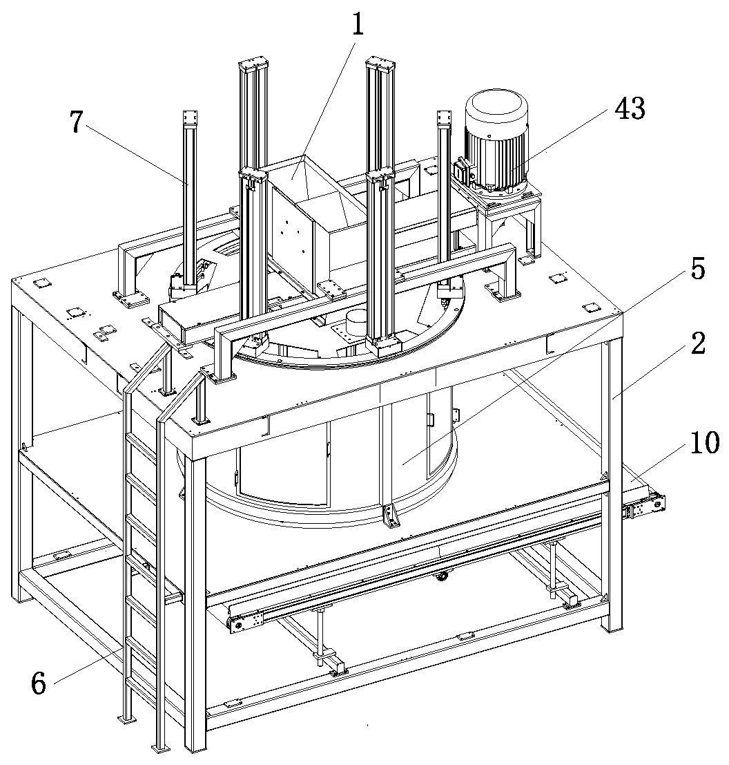
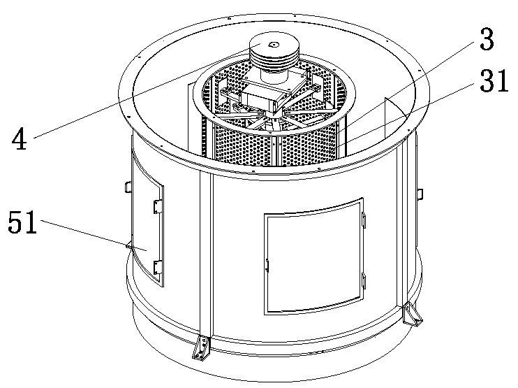
[0037] Such as figure 1 and figure 2 The high-speed mud cutting equipment shown includes a feed hopper 1, a mounting frame 2, a mud cutting bin 3, a mud cutting mechanism 4, and a mud retaining bin 5; the mud cutting bin 3 is cylindrical, and is fixedly installed on the mounting frame 2, the side wall of the mud cutting bin 3 is provided with some through holes 31, and the through holes 31 can be in shapes such as circle, ellipse or rhombus. The shape of the mud-shielding bin 5 is the same as that of the mud-cutting bin 3 and is cylindrical; In the present embodiment, the through holes 31 are circular holes and are evenly distributed on the side wall of the mud cutting bin 3. The diameter of the circular holes is about 3 cm. Of course, the diameter of the circular holes can also be selected according to the actual situation. Generally speaking When the diameter of the round hole is 1cm to 5cm, the effect is better.

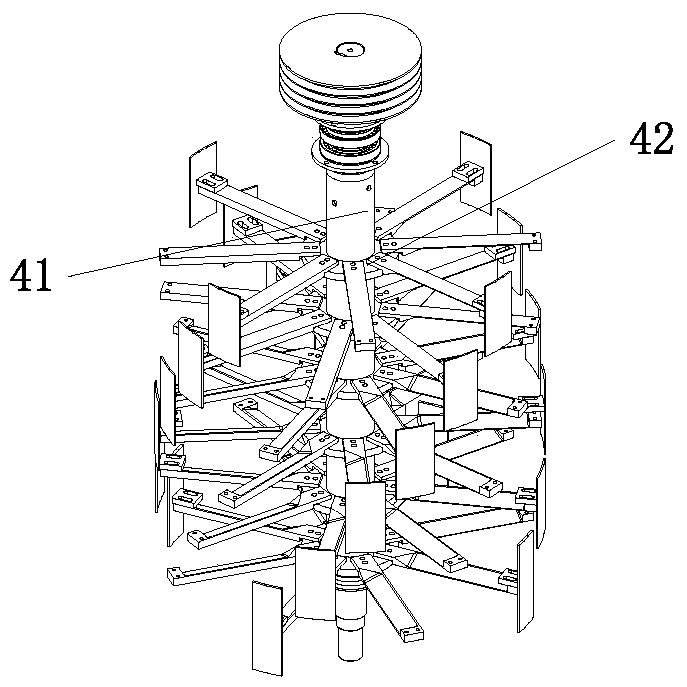
[0038] Such as figure 2 and image 3 As shown, the mu...

Embodiment 2

[0050] Some mud material to be cut has a large volume and heavy weight, so when it falls into the mud cutting bin 3 from the feed hopper 1, it will hit the mud cutting knife 421 rotating at a high speed, which will cause great damage to the mud cutting knife 421 and the rotating shaft 41. Big impact seriously affects the service life of the present invention. In order to solve this problem, this embodiment adds a crushing device 8 on the basis of Embodiment 1, and pre-crushes the mud entering the feed hopper 1 to reduce the volume of the large mud, so that it enters the mud cutting bin 3 The volume of the mud inside is relatively uniform.

[0051] The crushing device 8 is fixedly installed on the installation frame 2 and is located directly above the feed hopper 1 .

[0052] Such as Figure 8 As shown, the crushing device 8 includes a mounting bracket 81, a crushing bin 82, a screen 83, a breaking hammer assembly 84 and a motor A85. The crushing bin 82 is fixedly mounted on ...


PUM

PropertyMeasurementUnit
diameteraaaaaaaaaa
particle diameteraaaaaaaaaa

Abstract

The invention relates to the technical field of ceramic powder preparation equipment, in particular to high-speed mud cutting equipment. The high-speed mud cutting equipment comprises a mud cutting bin, a mud baffle bin and a mud cutting mechanism, wherein the mud cutting mechanism comprises a rotary shaft and mud cutting knife tackles; a rotary shaft can be rotatably mounted on the middle part ofthe mud cutting bin; the mud cutting knife tackles are sequentially arranged and fixedly mounted on the rotary shaft; the mud baffle bin sleeves the mud cutting bin; a plurality of through holes areformed in the mud cutting bin; a mud scraping knife is driven by the rotary shaft to rotate; a plurality of through holes are formed in the mud cutting bin; each mud cutting knife tackle comprises oneor more mud cutting knifes, and upper and lower adjacent mud cutting knifes are arranged in a staggered mode; the through holes are formed in the mud cutting bin, so that the size of mud adhered on the mud cutting bin can be reduced, and contact area between the mud and the mud cutting bin is reduced, and therefore, adhesion force is reduced, and mud is easily scraped off by the mud scraping knife; and the mud scraping knife can scrape off mud adhered on the inner wall of the mud cutting bin, so that the effect of clearing the inner wall of the mud cutting bin is achieved.

Description

technical field [0001] The invention relates to the technical field of ceramic powder preparation equipment, in particular to high-speed mud cutting equipment. Background technique [0002] In order to solve the problems of high energy consumption, serious pollution, and high production cost caused by the use of a spray drying tower to dry ceramic slurry, a Chinese invention patent application with application number 2019102196264 discloses a ceramic wet low-temperature powder-making process. Through dehydration, low-temperature drying and crushing of the slurry, the obtained dry powder particles have the characteristics of low water content. This process does not need to consume too much combustion energy while maintaining the efficiency of ceramic powder making. Significantly reduce the energy consumption of the ceramic production process, improve production efficiency, effectively reduce pollutants and greatly reduce the production cost of enterprises. [0003] In this p...

Claims


Application Information

Patent Timeline
Patent Type & Authority Applications(China)
IPC IPC(8): B28B11/14B02C13/13B02C13/06B02C13/26B02C23/16
CPCB02C13/06B02C13/13B02C13/26B02C23/16B02C2023/165B28B11/14
Inventor 李金华林庆生
Owner FOSHAN LANZHIJING SCI & TECH CO LTD
Why Eureka
Try Eureka