
System used for monitoring downhole dynamic parameters

A technology for dynamic parameters and well monitoring, applied in measurement, borehole/well components, earthwork drilling and production, etc., can solve the problem of lack of intelligent data analysis and diagnosis functions, lack of surface data analysis and processing and downhole risk warning functions, and high temperature resistance And other issues

Active Publication Date: 2020-07-07
CHINA PETROLEUM & CHEM CORP +1
View PDF7 Cites 7 Cited by
  • Summary
  • Abstract
  • Description
  • Claims
  • Application Information

AI Technical Summary

Problems solved by technology

[0004] To sum up, the existing dynamic parameter monitoring tools have the following problems: (1) The existing domestic engineering parameter measurement system has few data types and low precision, and the downhole measurement nipple is not resistant to high temperature, which cannot meet the needs of deep wells and ultra-deep wells. use
(2) The existing engineering parameter measurement system cannot realize real-time upload of monitoring data, and data analysis needs to be performed after drilling, which cannot guide the adjustment of drilling parameters in real time while drilling
(3) There is no intelligent data analysis and diagnosis function in the existing engineering parameter measurement sub-section data analysis after tripping out, lack of surface data analysis and processing and downhole risk warning function

Method used


Image

  • System used for monitoring downhole dynamic parameters
  • System used for monitoring downhole dynamic parameters
  • System used for monitoring downhole dynamic parameters

Examples


Embodiment 1

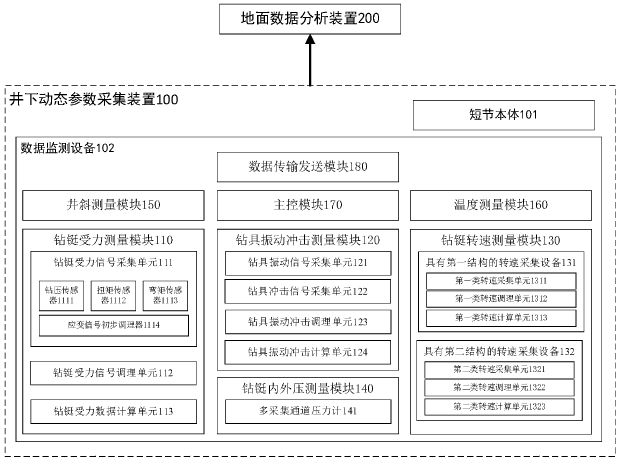
[0029] figure 1 It is a schematic diagram of the overall structure of a system for monitoring downhole dynamic parameters according to an embodiment of the present application. Such as figure 1 As shown, the system includes a downhole dynamic parameter acquisition device 100 and a surface data analysis module 200 . Wherein, the downhole dynamic parameter acquisition device 100 is arranged between the downhole measurement while drilling sub-joint and the drill bit. The downhole dynamic parameter acquisition device 100 is used to acquire downhole dynamic data (also called "downhole operating condition data") during the real-time drilling process of the drilling tool, perform downhole vibration analysis and calculation according to the downhole dynamic data, and combine the calculation results with the real-time collected data. The downhole dynamic data is integrated to obtain the dynamic information of the monitoring while drilling, and the dynamic data of the monitoring while...

Embodiment 2

[0037] The structure and function of each module in the above-mentioned data monitoring device 102 will be described below. Such as figure 1 As shown, the drill collar force measurement module 110 includes a drill collar force signal acquisition unit 111 , a drill collar force signal conditioning unit 112 and a drill collar force data calculation unit 113 .

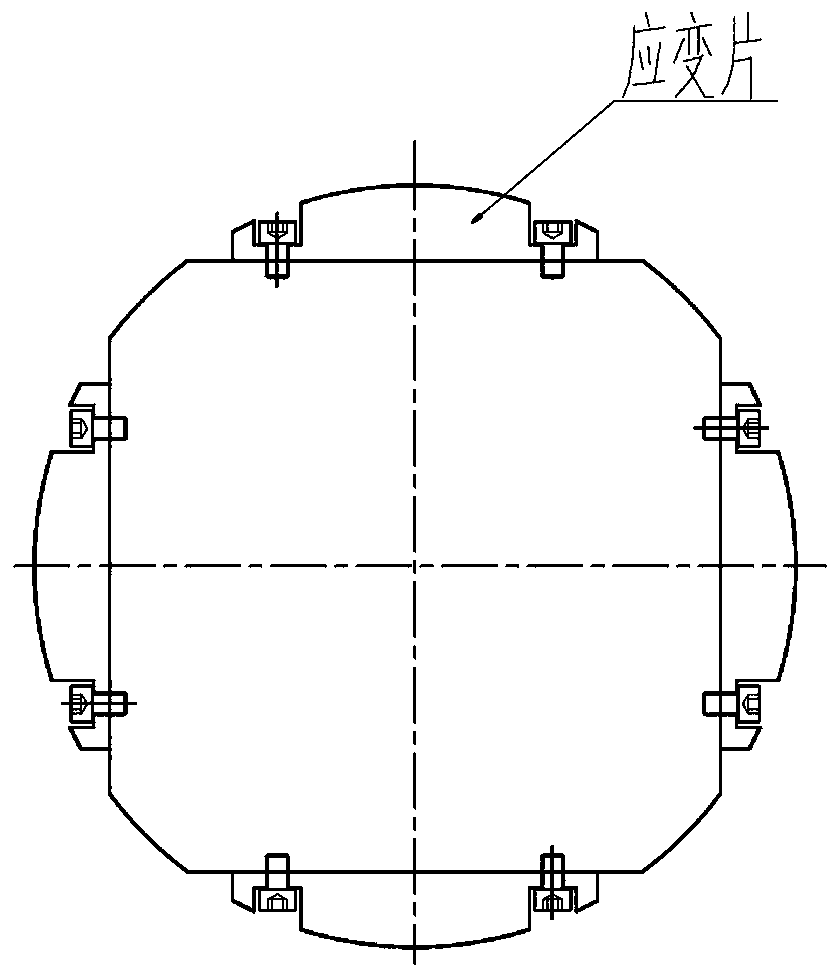
[0038] Specifically, the force signal acquisition unit 111 of the drill collar is arranged in the radial direction of the inner wall of the drill collar, and is used to collect the pressure-on-bit signal, the torque signal and the bending moment signal respectively. Wherein, the force signal acquisition unit 111 of the drill collar includes: several weight-on-bit sensors 1111 , several torque sensors 1112 and several bending moment sensors 1113 . Further, the weight-on-bit sensor 1111, and / or the torque sensor 1112, and / or the bending moment sensor 1113 are arranged along the rotation axis of the drilling tool, and are e...

Embodiment 3

[0051] The structure and function of each module in the above-mentioned data monitoring device 102 will be further described below based on the second embodiment. Such as figure 1 As shown, the drilling tool vibration impact measurement module 120 includes a drilling tool vibration signal acquisition unit 121 , a drilling tool impact signal acquisition unit 122 , a drilling tool vibration impact conditioning unit 123 , and a drilling tool vibration impact calculation unit 124 .

[0052] Wherein, the drilling tool vibration signal acquisition unit 121 is installed on the skeleton of the pup joint body 101 for real-time acquisition of the three-axis vibration signal of the downhole drilling tool. This facilitates monitoring and downhole vibration analysis including axial and radial vibration levels. In the embodiment of the present invention, the drilling tool vibration signal acquisition unit 121 uses a three-axis vibration sensor to complete the acquisition of three-axis vibr...


PUM


Abstract

The invention discloses a system used for monitoring downhole dynamic parameters. The system comprises a downhole dynamic parameter acquisition device and a ground data analysis device. The downhole dynamic parameter acquisition device is arranged between a downhole measurement while drilling nipple and a drill bit and is used for obtaining downhole dynamic data of the real-time drilling process of a drilling tool, conducting downhole vibration analytical calculation according to the downhole dynamic data, integrating the calculation result and the downhole dynamic data, obtaining monitoring while drilling dynamic information and conducting output, wherein downhole vibration analytical calculation includes drilling tool stick-slip severity calculation and drilling tool turbine severity calculation. The ground data analysis device is used for obtaining the while-drilling monitoring dynamic information in real time and diagnosing the while-drilling monitoring dynamic information and analyzing the drilling tool drilling risk through combination with current ground well drilling parameters and is used for adjusting and optimizing well drilling guide control parameters in real time. Bymeans of the system, drilling tool harmful vibration can be avoided, the penetration rate can be increased, the drill bit service life can be prolonged, the drilling tool failure can be reduced, efficiency and benefit evaluation of downhole speed increase tools and auxiliary tools is achieved, and the well drilling efficiency is improved.

Description

technical field [0001] The invention relates to the field of downhole measurement while drilling in oil and gas well engineering, in particular to a system for monitoring downhole dynamic parameters. Background technique [0002] Domestic research on downhole dynamic parameter monitoring began in the 1980s. Although some achievements have been made, at present it basically stays in theoretical research and laboratory experiments, and there is no practical monitoring tool for downhole dynamic parameters while drilling. Mainly limited by factors such as high temperature, strong vibration, large amount of data, and small mechanical space, the continuous acquisition and storage of downhole dynamic signals has always been a difficult point in the design of drilling tools. High-speed data acquisition, storage, and data calculation in real-time state Higher technical requirements are put forward for the monitoring system. In 1998, Guo Xuezeng and others developed a set of surface ...

Claims


Application Information

Patent Timeline
IPC IPC(8): E21B47/00E21B47/06E21B47/12
CPCE21B47/00E21B47/06E21B47/12Y02T90/00
Inventor 宗艳波曾义金胡群爱张卫孙明光孙峰郑俊华钱德儒王磊宋朝晖
Owner CHINA PETROLEUM & CHEM CORP
Learn More