
Small-outer-diameter single-mode optical fiber

A technology of single-mode optical fiber and small outer diameter, which is applied in the field of optical communication transmission, and can solve problems such as the influence of optical fiber microbending performance, long production process route, and complex outer cladding design.

Active Publication Date: 2020-07-07
YANGTZE OPTICAL FIBRE & CABLE CO LTD
View PDF11 Cites 2 Cited by
  • Summary
  • Abstract
  • Description
  • Claims
  • Application Information

AI Technical Summary

Problems solved by technology

The function of the first layer of coating is to buffer the external force on the optical fiber. It is very important to improve the microbending performance of the optical fiber. The thickness of the first layer of coating is too low. In order to ensure the microbending of the optical fiber, the performance of the coating will be too high, which is not conducive to Mass production and application
[0009] US Patent US20180203184A1 describes a small outer diameter optical fiber, and designs the composition of the optical fiber coating, but does not mention how to improve the microbending performance of the optical fiber by optimizing the curing conditions. In fact, in addition to the design of the coating components, the optical fiber coating Curing conditions also have a great influence on the microbending performance of optical fibers
[0010] US patent US20190049660A1 describes a series of optical fibers with bending performance meeting G.657.A1. Most of the refractive index profiles are designed with a depressed outer cladding. Although a few refractive index profiles include a depressed inner cladding structure, the design of the outer cladding is very complicated and the production process is long. , high cost, not conducive to mass production

Method used


Image

  • Small-outer-diameter single-mode optical fiber
  • Small-outer-diameter single-mode optical fiber
  • Small-outer-diameter single-mode optical fiber

Examples


Embodiment Construction

[0037] The present invention will be described in further detail below in conjunction with the embodiments and accompanying drawings.

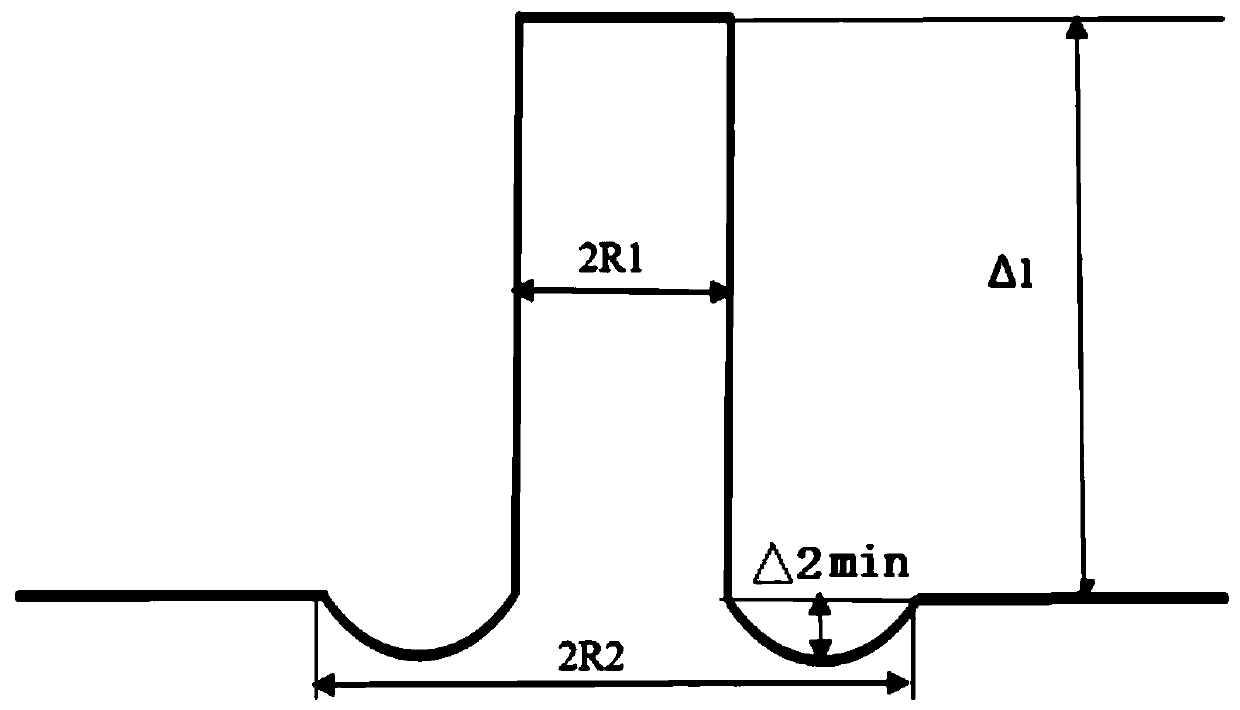
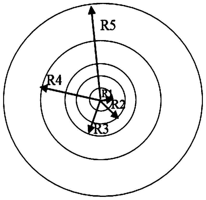
[0038] The optical fiber includes a core layer, a sunken inner cladding layer, an outer cladding layer, an inner coating layer, and an outer coating layer from the inside to the outside, wherein the core layer, the sunken inner cladding layer, and the outer cladding layer are silica glass parts of the optical fiber, and the inner coating layer and the outer coating layer is the resin coating layer of the optical fiber; the diameter of the core layer is 2R1, the relative refractive index difference is Δ1, the diameter of the sunken inner cladding is 2R2, and the refractive index distribution of the sunken inner cladding is concave, so The relative refractive index difference between the inner edge and the outer edge of the depressed inner cladding layer is flush and equal to the relative refractive index difference Δ3 of the outer cladding layer...


PUM


Abstract

The invention relates to a small-outer-diameter single-mode optical fiber, which comprises a core layer and a cladding, and is characterized in that the diameter 2R1 of the core layer is 7.0-7.4[mu]m,the relative refractive index difference is [delta]1, the cladding sequentially comprises a sunken inner cladding and an outer cladding from inside to outside, the diameter 2R2 of the sunken inner cladding is 26-34[mu]m, the refractive index of the sunken inner cladding is distributed in a sunken shape, the minimum relative refractive index difference is [delta]2min, the refractive index difference [delta]total between the core layer and the inner cladding is equal to ([delta]1-[delta]2min), the range of [delta]total is 0.37-0.44%, and the relative refractive index difference distribution relationship between the core layer and the sunken inner cladding meets the following condition: the absolute value of [delta]1 / [delta]2min ranges from 7.5 to 10, the outer cladding is a pure silicon dioxide outer cladding, the relative refractive index difference [delta]3 of the outer cladding is 0%, the diameter 2R3 of the outer cladding is 124-126[mu]m, the outer cladding is coated with an inner coating and an outer coating, the diameter 2R4 of the inner coating is 150-170[mu]m, and the diameter 2R5 of the outer coating is 180-220[mu]m. Through optimization of a section structure and a coatingprocess, the optical fiber not only has a large mode field diameter, but also has low bending loss and good micro-bending performance.

Description

technical field [0001] The invention relates to a single-mode optical fiber with small outer diameter and low bending loss, which belongs to the field of optical communication transmission. Background technique [0002] With the continuous development of FTTx, in many cases, the optical fiber will face complex construction environments such as the interior of the residential area and the corner of the corridor, which requires the optical fiber to have a certain bending resistance, so that it can still ensure the normal signal under the condition of a small bending radius For transmission, on the other hand, with the increasing shortage of urban pipeline resources, it is required that the outer diameter of the optical fiber can be reduced while ensuring the same microbending performance as the traditional outer diameter optical fiber. [0003] G.657.A1 optical fiber can be used under the condition of at least 10mm bending radius, which meets the FTTx use environment. In orde...

Claims


Application Information

Patent Timeline
IPC IPC(8): G02B6/02G02B6/028G02B6/036C03C25/106
CPCC03C25/106G02B6/02266G02B6/02395G02B6/0286G02B6/03633G02B6/03644G02B6/0365
Inventor 杨柳波张磊李鹏沈磊吴超
Owner YANGTZE OPTICAL FIBRE & CABLE CO LTD
Learn More