Non-rotary computer tomography imaging device and method

A technology of tomographic imaging and imaging method, which is applied in computerized tomography scanners, diagnosis, echo tomography, etc., can solve the problems of small number of ray source layouts, missing data, incomplete data, etc., to improve image reconstruction quality, reduce Effects of missing data and improving inspection speed

Pending Publication Date: 2020-07-10
王振
View PDF5 Cites 4 Cited by
  • Summary
  • Abstract
  • Description
  • Claims
  • Application Information

AI Technical Summary

Problems solved by technology

Patents CN103340641A and CN201210211462.9 disclose a double-ring structure, including a ray source in a ring layout and a detector in a ring layout. There is a gap between the detectors in the ring layout, and the gap is for the ray to pass through to reach the ring detector. In the detection unit on the other side, the existence of gaps will lead to data loss and reduce image quality. This structure also has another disadvantage, that is, the axial scan cannot obtain the data of the central slice.
The static CT scanner disclosed in the patent CN201110247455 is also a double-ring structure, but the radiation source and the detector are misplaced in the moving direction of the object to be detected. In this scanning structure, the radiation does not face the detector directly, but passes obliquely through the object, and the collected data is seriously missing. The condition of data completeness is seriously not satisfied, and the analytical reconstruction method is used to reconstruct the image, and the reconstruction accuracy is low
The image quality can be improved to a certain extent through the 3D iterative reconstruction algorithm, but the computational efficiency of the 3D iterative reconstruction algorithm is still difficult to meet the needs of practical applications. Of course, even if iterative reconstruction is used, the quality of the reconstructed image cannot reach that of the ray source because the data seriously does not meet the tuy condition. At the level facing the detector, the image quality requirements of medical CT imaging are very high, so this structure has obvious defects for medical CT imaging
[0004] In the field of security inspection CT, the American Rapiscan Company and Surescan Company have their own static CT products and corresponding patents such as US8451974B2 and US20060227932A1. The products of the American Rapiscan Company (such as the patent US8451974B2) adopt a double-ring structure. The ray source and the detector in the circular layout are similar to the patent CN201110247455. The ray source and the detector are misplaced in the moving direction of the object to be detected, and there is a shortcoming of incomplete data caused by the same oblique shot
Surescan's products (such as patent US20060227932A1) adopt a three-level scanning mode, each level has multiple ray sources and a line array detector, and the ray sources are quickly switched to simulate rotational motion. This scanning mode is a multi-level static scanning mode; The advantage is that the ray source can face the detector directly, and the linear array detector can also effectively suppress scattering through post-collimation. However, due to the small number of ray source layouts in this scheme, the image quality after iterative reconstruction is still relatively low; at the same time, due to the The three-level scanning mode is adopted, which makes the length of the equipment relatively large; in addition, since multiple ray sources share a line array detector at each level, the projection data of the scanned object is missing, which will also reduce the quality of the reconstructed image

Method used


Image

  • Non-rotary computer tomography imaging device and method
  • Non-rotary computer tomography imaging device and method
  • Non-rotary computer tomography imaging device and method

Examples


Embodiment Construction

[0063] The technical solutions of the present invention will be described in further detail below with reference to the accompanying drawings and embodiments. Although exemplary embodiments of the present disclosure are shown in the drawings, it should be understood that the present disclosure may be embodied in various forms and should not be limited by the embodiments set forth herein. Rather, these embodiments are provided for more thorough understanding of the present disclosure and to fully convey the scope of the present disclosure to those skilled in the art.

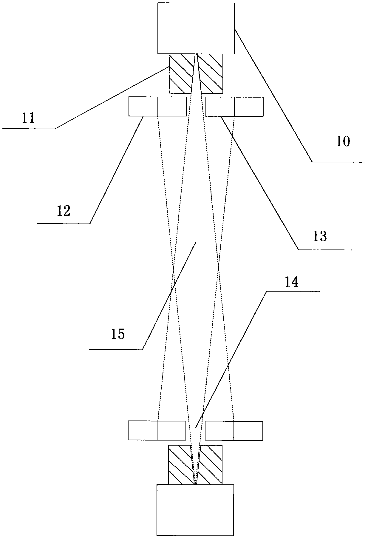
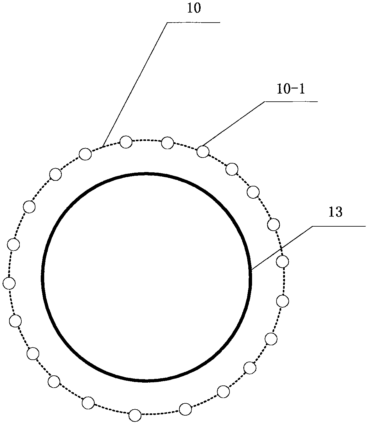
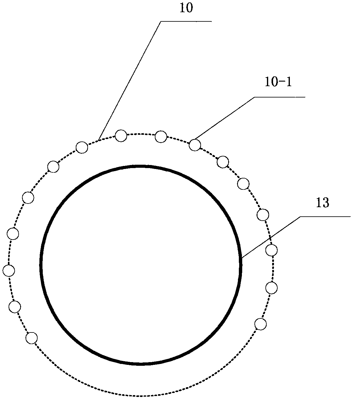
[0064] A non-rotating computed tomography device includes: a ray source, a detector, a collimator, a transmission device for transporting a detected object, and a computer device for control and data processing. It is characterized in that: the ray source is arranged in an annular distributed ray source 10 on the outer ring, and the detector is an annular detector 13 arranged on the inner ring.

[0065] The dist...


PUM


Abstract

The invention discloses a non-rotary computer tomography imaging device and method. The device comprises a distributed radiation source arranged on an outer ring, an annular detector arranged on an inner ring, a transmission device used for conveying an object to be detected and a computer device used for control and data processing. The detector is divided into three sections, namely a central part and two side parts, along the traveling direction of the detected object, and the central part is a single-layer single-energy detector. According to the imaging method, at least one radiation source works simultaneously, and the radiation sources are rapidly switched. In an imaging process, the radiation source limits the beam range, so that radiation only passes through the central part of one side, close to one side of the radiation source emitting the radiation, of the annular detector, and the detector on the other side of the annular detector receives the radiation to realize signal acquisition. The imaging method also comprises a processing method of projection data, wherein beam hardening correction is carried out on signals of the central part detector and the two side part detectors, and the signals are unified to same radiation energy. The scheme of the invention can obviously improve the quality of computed tomography imaging.

Description

technical field [0001] The invention belongs to the field of computerized tomography (CT) scanners, in particular to a non-rotating computerized tomography device and method. It can be used in the fields of medicine, security inspection, and industrial inspection. Background technique [0002] CT equipment is widely used in medical, security inspection and industrial fields. In the field of medical and security inspection applications, the mainstream scanning mode is still a rotary scan in which the radiation source and detector rotate around the detected object. The so-called "fifth generation CT" has appeared in the history of medical CT equipment, that is, GE's electron beam scanning CT (E-beam CT), which uses a large-scale scanning electron beam ray tube, and simulates the focus of the ray source through the rapid deflection of the electron beam. Rapid rotation movement, CT scanning can be completed without the rotation of the radiation source and the detector. Howeve...

Claims


Application Information

Patent Timeline
IPC IPC(8): A61B6/03
CPCA61B6/032A61B6/4014
Inventor 王振
Owner 王振
Why Eureka
Try Eureka