Trigger and protection circuit of excimer laser high-voltage switch

An excimer laser, high-voltage switch technology, applied in emergency protection circuit devices, phonon exciters, circuits, etc., can solve problems such as interference and damage to trigger circuits, and achieve the effect of reducing interference

Pending Publication Date: 2020-07-14
HEFEI INSTITUTES OF PHYSICAL SCIENCE - CHINESE ACAD OF SCI
View PDF0 Cites 2 Cited by
  • Summary
  • Abstract
  • Description
  • Claims
  • Application Information

AI Technical Summary

Problems solved by technology

This spike interference voltage will disturb and damage the low-voltage components in the trigger circuit

Method used


Image

  • Trigger and protection circuit of excimer laser high-voltage switch
  • Trigger and protection circuit of excimer laser high-voltage switch
  • Trigger and protection circuit of excimer laser high-voltage switch

Examples


Embodiment 1

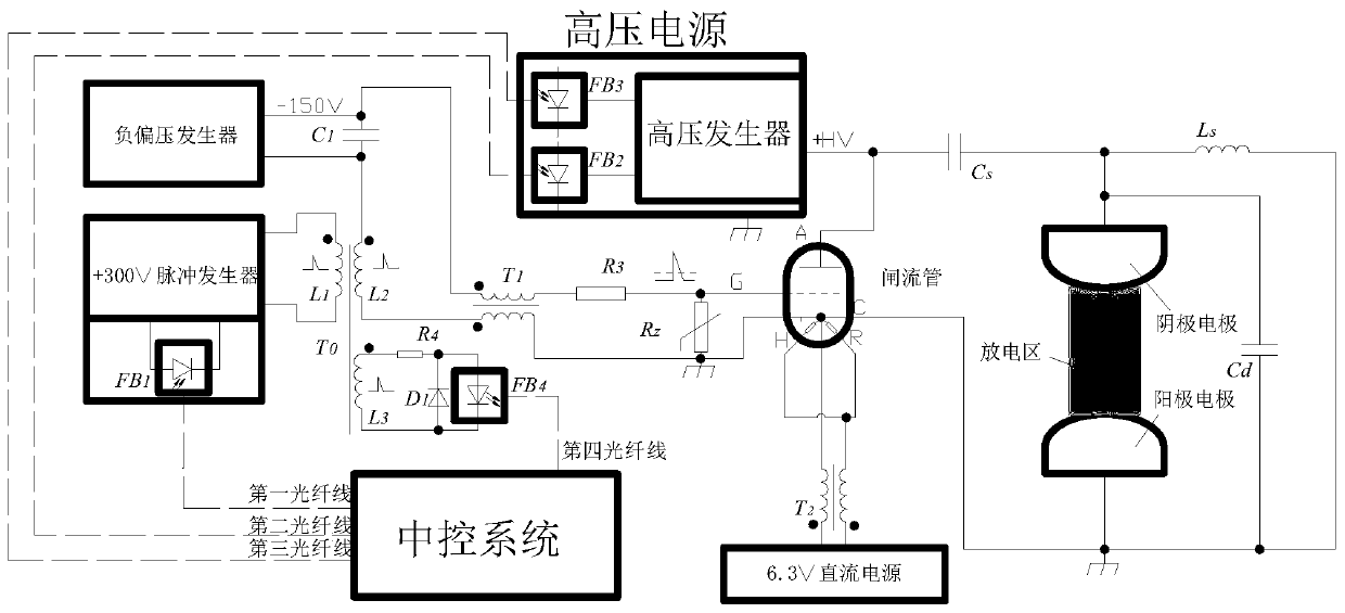
[0066] Embodiment 1. The high-voltage switch is a trigger and protection circuit of a hydrogen thyratron

[0067] Depend on figure 1 As shown, the circuit includes: central control system, high voltage generator, pulse generator, negative bias generator, hydrogen thyratron, capacitor C 1 , Transformer T 0 , Divider resistance R 4 , Diode D 1 , common mode choke coil T 1 , current limiting resistor R 3 , Varistor R Z , common mode choke coil T 2 , inductance L S , discharge capacitor C d , Energy storage capacitor C S , cathode electrode, anode electrode, fiber optic head FB 1 , Fiber head FB 2 , Fiber head FB 3 , Fiber head FB 4 ,DC power supply.

[0068] The central control system generates an optical pulse width signal and a charging reference voltage optical signal; the optical pulse width signal is used to indicate the time of light; the charging reference voltage optical signal is used to indicate the magnitude of the final charging voltage.

[0069] The ce...

Embodiment 2

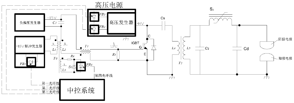
[0108] Embodiment 2, the high-voltage switch is an IGBT, that is, a trigger and protection circuit of an insulated gate bipolar transistor

[0109] Depend on image 3 As shown, the circuit includes: central control system, pulse generator, negative bias generator, high voltage generator, IGBT, capacitor C 1 , Transformer T 0 , Divider resistance R 4 , Diode D 1 , common mode choke coil T 1 , Snubber resistance R 1 , Transformer T 2 , Energy storage capacitor C S , Voltage doubling capacitor C 2 , discharge capacitor C d , cathode electrode, anode electrode, fiber optic head FB 1 , Fiber head FB 2 , Fiber head FB 3 , Fiber head FB 4 , magnetic switch S 2 .

[0110] The central control system generates an optical pulse width signal and a charging reference voltage optical signal; the optical pulse width signal is used to indicate the time of light; the charging reference voltage optical signal is used to indicate the magnitude of the final charging voltage.

[011...


PUM


Abstract

The invention discloses a trigger and protection circuit for an excimer laser high-voltage switch. A central control system transmits a generated optical pulse width signal to a pulse generator and ahigh-voltage generator synchronously; the central control system also transmits a generated charging reference voltage optical signal to the high-voltage generator; a transformer T0 comprises a primary coil L1, a secondary coil L2 and a secondary coil L3; two ends of the primary coil L1 of the transformer T0 are connected with the pulse generator; two ends of the secondary coil L2 of the transformer T0 are respectively connected with the core axis and shielding layer of a common mode choke T1; two ends of the secondary coil L3 of the transformer T0 are connected with a voltage dividing resistor R4; the voltage dividing resistor R4 forms a feedback unit and is used for generating a feedback signal and feeding back whether the pulse generator generates a trigger signal or not; and the central control system is connected with the feedback unit and used for receiving the feedback signal generated by the feedback unit. According to the circuit of the invention, the trigger signal of the high-voltage switch can be generated and the high-voltage switch has the capability of resisting high-voltage spike pulse interference, so that the high-voltage switch can work stably for a long time.

Description

technical field [0001] The invention relates to the technical field of high-voltage switch control, in particular to a trigger and protection circuit of an excimer laser high-voltage switch. Background technique [0002] Excimer lasers need to work at high voltages. High-voltage switches such as IGBTs and hydrogen thyratrons are two typical switches used in high-voltage circuits, because high-voltage switches will couple tens to thousands of volts of spike interference voltage at the trigger terminal during the conduction process. This spike interference voltage will disturb and damage the low-voltage components in the trigger circuit. Therefore, a special circuit is needed to generate the trigger signal of the high-voltage switch and it should have the ability to resist spike voltage interference, so that the high-voltage switch can work stably for a long time. Contents of the invention [0003] In order to overcome the defects in the above-mentioned prior art, the pres...

Claims


Application Information

Patent Timeline
IPC IPC(8): H01S3/11H02H7/20
CPCH01S3/11H02H7/205
Inventor 梁勖朱能伟林颖方晓东
Owner HEFEI INSTITUTES OF PHYSICAL SCIENCE - CHINESE ACAD OF SCI
Why Eureka
Try Eureka