Eureka AIR delivers breakthrough ideas for toughest innovation challenges, trusted by R&D personnel around the world.

Light hydrocarbon oil gas recovery system carrying associated gas

An oil and gas recovery system and associated gas technology, applied in the direction of steam condensation, chemical instruments and methods, separation methods, etc., can solve the problems of dispersed and small amount of associated gas, economic loss, good volatility, etc., to reduce unsafe factors, The effect of increasing economic benefits and avoiding environmental pollution

Pending Publication Date: 2020-07-17
天津绿州能源装备有限公司
View PDF0 Cites 0 Cited by
  • Summary
  • Abstract
  • Description
  • Claims
  • Application Information

AI Technical Summary

Problems solved by technology

The associated gas in existing scattered and remote well areas is scattered and the amount is small, away from the natural gas pipeline network, the oil and gas volatilized from the crude oil storage tank carrying the associated gas are generally burned through the torch, and the volatilized oil and gas are mainly CH 4 、C 2 h 6 、C 3 h 8 、C 4 h 10 The light hydrocarbon itself is a very clean fuel. The main component of light oil is a mixture of C5-C8 hydrocarbons, and contains a small amount of hydrocarbons larger than C8, as well as sulfur dioxide, thiophenes, mercaptans, sulfides and more. For impurities such as sulfides, its fractions are mostly at 20°C to 200°C, and its specific gravity is less than 0.78. The content of heavy hydrocarbons and non-hydrocarbon components is lower than that of crude oil, and its volatility is good. About 1% loss is caused by oil and gas volatilization every year. Discharging into the air is not only a waste, but also flammable gas is discharged into the air, which has potential risks, pollutes the environment, and causes economic losses at the same time

Method used


Image

  • Light hydrocarbon oil gas recovery system carrying associated gas

Examples


Embodiment Construction

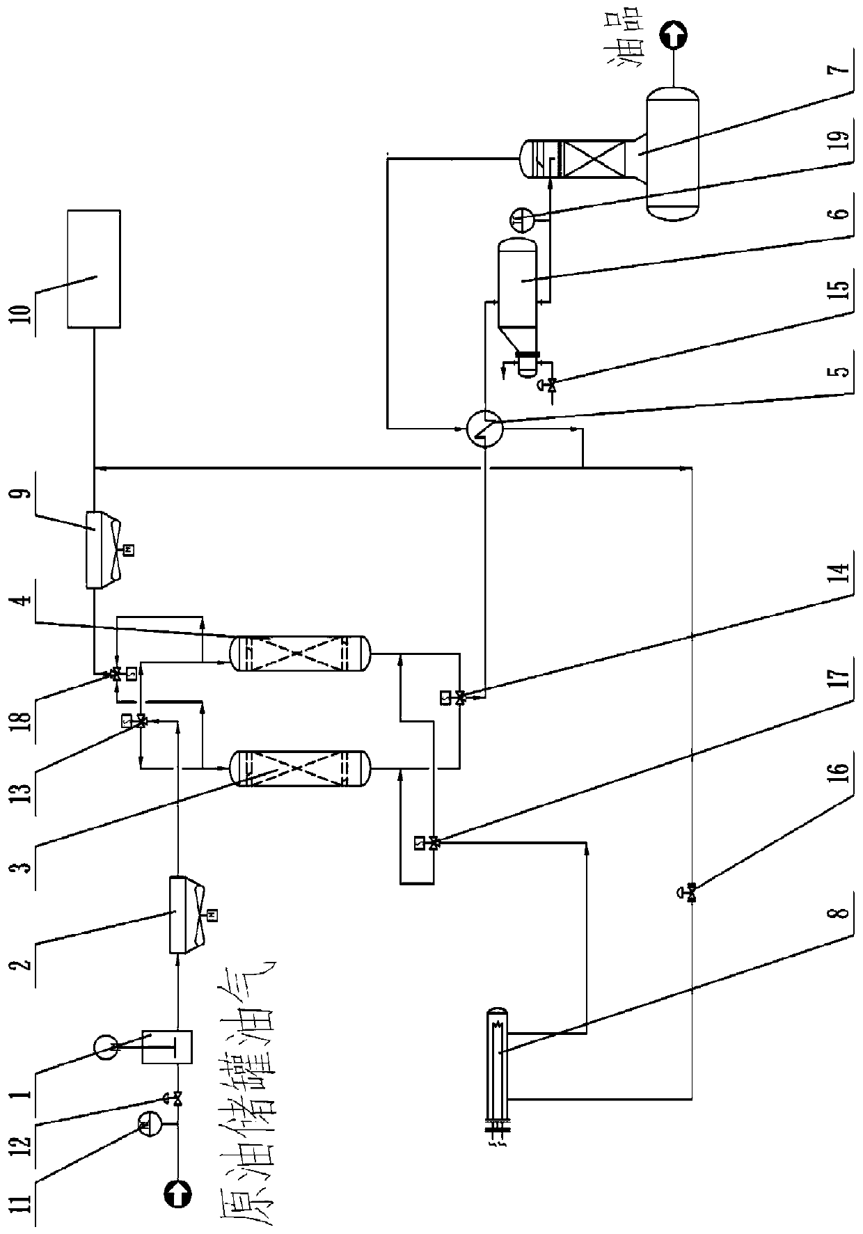
[0015] A light hydrocarbon oil and gas recovery system carrying associated gas, including raw gas compressor 1, air cooler 2, molecular sieve tower A3 and molecular sieve tower B4, precooler 5, evaporator 6, deethanizer 7, crude oil storage tank volatilization The oil and gas coming out are transported through the pipeline to the raw material gas compressor 1 for pressurization, the raw material gas compressor 1 is connected to the air cooler 2 through the pipeline, and the air cooler 2 is divided into two branch pipelines through the pipeline, and the two branch pipelines are respectively connected to the molecular sieve tower A3 and The air inlet of molecular sieve tower B4, the gas outlets of molecular sieve tower A3 and molecular sieve tower B4 are connected to precooler 5 through pipelines, precooler 5 is connected to evaporator 6 through pipelines, and the condensation outlet of evaporator 6 is connected to deethylation through pipelines The air inlet of the alkane tower ...


PUM


Abstract

The invention discloses a light hydrocarbon oil gas recovery system carrying associated gas. The system comprises a feed gas compressor, an air cooler, two molecular sieve towers, a precooler, an evaporator and a deethanization tower; the oil gas volatilized from the crude oil storage tank is conveyed to the feed gas compressor through a pipeline for pressurization; the feed gas compressor is connected with the air cooler through a pipeline; wherein the air cooler is divided into two branch pipelines through a pipeline, the two branch pipelines are respectively connected to an air inlet of themolecular sieve tower, an air outlet of the molecular sieve tower is connected to the precooler through a pipeline, the precooler is connected with the evaporator through a pipeline, a condensation outlet of the evaporator is connected to an air inlet of the deethanization tower through a pipeline, and an oil outlet of the deethanization tower collects finished products. Combustion of the oil gasvolatilized from crude oil storage tanks in existing scattered and remote well areas is eliminated, environmental pollution is avoided, the volatilized oil gas is recycled, energy is saved, economicbenefits are increased, and meanwhile unsafe factors are reduced.

Description

technical field [0001] The invention relates to an oil gas recovery system, in particular to a light hydrocarbon oil gas recovery system carrying associated gas. Background technique [0002] Since the Industrial Revolution, oil has become the blood of social progress and industrial development. At the same time, for most countries in the world, oil is still an important strategic resource for maintaining national security, and its importance is self-evident. The associated gas in existing scattered and remote well areas is scattered and the amount is small, away from the natural gas pipeline network, the oil and gas volatilized from the crude oil storage tank carrying the associated gas are generally burned through the torch, and the volatilized oil and gas are mainly CH 4 、C 2 h 6 、C 3 h 8 、C 4 h 10 The light hydrocarbon itself is a very clean fuel. The main component of light oil is a mixture of C5-C8 hydrocarbons, and contains a small amount of hydrocarbons larger...

Claims


Application Information

Patent Timeline
Patent Type & Authority Applications(China)
IPC IPC(8): B01D5/00
CPCB01D5/0057
Inventor 谢广禄
Owner 天津绿州能源装备有限公司
Why Eureka
Eureka Blog
Learn More