Metal coil splitting machine

A technology of metal coils and slitting machines, which is applied to metal processing machinery parts, metal processing equipment, shearing devices, etc., to achieve the effects of reducing work load, delaying wear, and solving quality defects

Inactive Publication Date: 2020-07-17
南京百泽机械有限公司
View PDF9 Cites 2 Cited by
  • Summary
  • Abstract
  • Description
  • Claims
  • Application Information

AI Technical Summary

Problems solved by technology

[0006] Aiming at the problem that the upper slitting knife wears too fast in the existing battery pole piece slitting machine, the present invention provides a metal coil slitting machine, which can timely and effectively remove the edge of the upper slitting knife during the working process. Metal cutting and dust adhered to the upper surface, while reducing the temperature of the upper slitting knife edge, effectively delaying the wear of the upper slitting knife

Method used


Image

  • Metal coil splitting machine
  • Metal coil splitting machine
  • Metal coil splitting machine

Examples


Embodiment 1

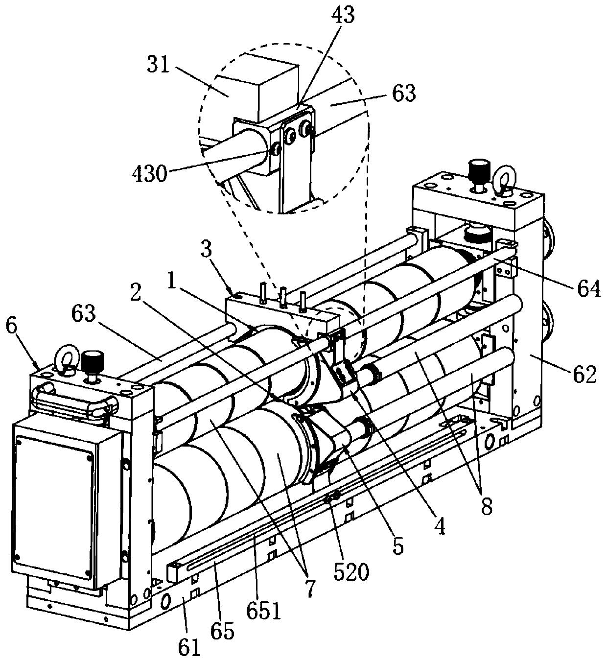
[0042] Such as figure 1 As shown in , the traditional battery pole piece slitting machine includes an upper shaft and a lower shaft arranged in parallel up and down. And two columns 62 that are vertically arranged on the base 61, the upper rotating shaft and the lower rotating shaft are horizontally arranged between the two columns 62; Knife 2 and two splitting knives are fixed on the rotating shaft through the spacer 7. It is understandable that the upper splitting knife 1 and the lower splitting knife 2 can be fixed on the two rotating shafts by using the hydraulic locking knife seat instead of the spacer 7. Above, the upper slitting knife 1 and the lower slitting knife 2 are co-located up and down, and the battery electrode coil to be slit is cut by the two slitting knives after passing between the upper slitting knife 1 and the lower slitting knife 2 cut apart.

[0043] During the use of this slitting machine, the upper cutting knife 1 wears too fast, resulting in a high...

Embodiment 2

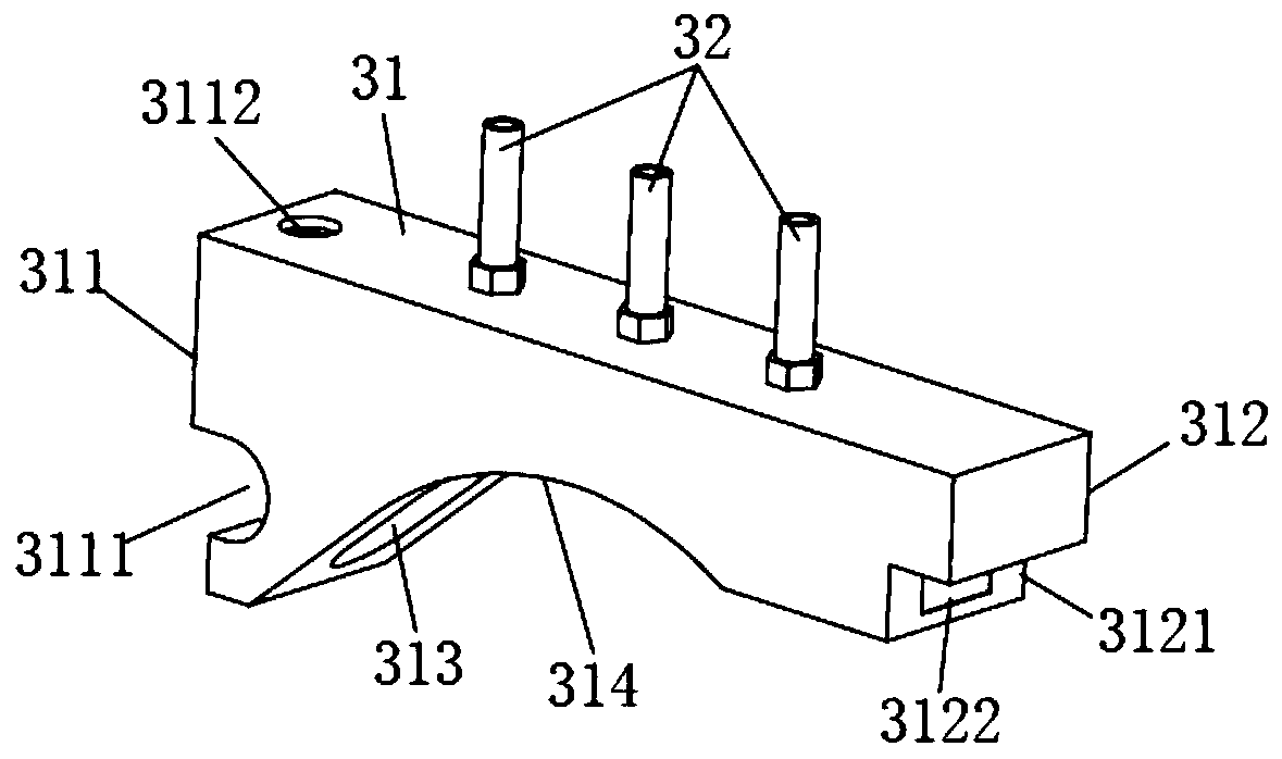
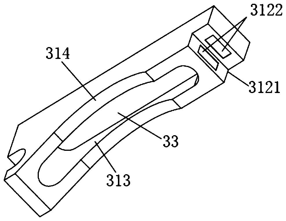
[0052] A kind of metal coil cutting machine of the present embodiment, basic structure is the same as embodiment 1, and difference and improvement are, as figure 2 with image 3 As shown in , the abutment 31 has a first connecting end 311 and a second connecting end 312, the first connecting end 311 has a side slot 3111, and the upper side of the abutment 31 is provided with a The fastening bolt I 3112 in the card slot 3111; the second connecting end 312 has a step bayonet 3121, and the inner side of the step bayonet 3121 is provided with a magnetic piece 3122, and the magnetic piece 3122 is preferably a permanent magnet alloy block .

[0053] During installation, the side clamping groove 3111 is clamped on the first crossbar 63, and the step bayonet 3121 is clamped on the second crossbar 64 at the same time, after the position is adjusted, tighten the fastening bolts I3112 fixes the first connecting end 311, and the second connecting end 312 is sucked and fixed on the seco...

Embodiment 3

[0055] A kind of metal coil slitting machine in the present embodiment, basic structure is the same as embodiment 2, and difference and improvement are, as figure 1 As shown in , it also includes an upper dust suction cover assembly 4, which is covered on the outside of the upper cutting knife 1; and a lower dust suction cover assembly 5, which is covered on the outside of the lower cutting knife 2; the upper dust suction The cover assembly 4 and the lower dust suction cover assembly 5 are used to absorb debris and dust generated by the slitting process. The upper dust suction hood assembly 4 and the lower dust suction hood assembly 5 are respectively connected to an external dust suction device through flexible connecting pipes 8 .

[0056] After the knife surface cleaning device 3 is installed on the slitting machine, although it can protect the upper slitting knife 1, the debris and dust generated by the slitting cannot be removed in time, resulting in a large amount of deb...


PUM


Abstract

The invention discloses a metal coil splitting machine, and relates to the technical field of splitting machines. The metal coil splitting machine comprises an upper rotating shaft, a lower rotating shaft, an upper slitting cutter, a lower slitting cutter, a cutter face cleaning device, an upper dust suction hood assembly and a lower dust suction hood assembly, wherein the upper rotating shaft andthe lower rotating shaft are arranged in parallel up and down, the upper slitting cutter and the lower slitting cutter are arranged on the two rotating shafts in a cooperative mode, the cutter face cleaning device comprises a base table, a liquid guide pipe and a flexible liquid immersion part, a containing cavity used for containing the upper slitting cutter is formed in the lower side face of the base table, the flexible liquid immersion part is contained in the containing cavity, the liquid guide pipe is led into the containing cavity from the upper side of the base table so as to convey cleaning liquid to the flexible liquid immersion part, the cutter face cleaning device covers the outer side of the upper slitting cutter and is used for wiping the upper slitting cutter, and the upperdust suction hood assembly and the lower dust suction hood assembly cover the outer side of the upper slitting cutter and the outer side of the lower slitting cutter respectively and are used for sucking away dust generated by slitting machining. According to the metal coil splitting machine, metal cuttings and dust which adhere to the blade part of the upper splitting cutter can be effectively removed in time in the working process, meanwhile, the temperature of the blade part of the upper splitting cutter is reduced, and abrasion of the upper splitting cutter is effectively delayed.

Description

technical field [0001] The invention relates to the technical field of slitting machines, in particular to a metal coil slitting machine. Background technique [0002] Lithium batteries have high working voltage, large specific energy, small size, light weight, long cycle life, low self-discharge rate, no memory effect, no pollution, etc., so they are used by many power equipment manufacturers. In the lithium battery manufacturing process, the battery pole sheet coil with a large width needs to be slitting and cut longitudinally into a specified width before use. [0003] At present, the battery pole piece slitting process adopts a special cutter, which includes an upper slitting knife and a lower slitting knife that cooperate with each other, wherein the upper slitting knife and the lower slitting knife are respectively fixed on the first knife axis and the second tool axis. However, when using a slitting knife to cut the battery pole sheet coil, a large amount of dust wi...

Claims


Application Information

Patent Timeline
IPC IPC(8): B23D19/04B23Q11/00B23Q11/10B08B1/02B08B13/00B08B15/04
CPCB23D19/04B23Q11/0046B23Q11/10B08B13/00B08B15/04B08B1/20B08B1/143
Inventor 袁雨柳开平
Owner 南京百泽机械有限公司
Why Eureka
Try Eureka