Construction method of invisible natural ventilation and drainage system for thermal insulation planting roof

A natural ventilation, thermal insulation technology, applied in the ventilation system, roof ventilation, roof drainage, etc., can solve the problem of cracking of concrete protective layer and coil, poor appearance and practical performance of roof decoration, water accumulation in insulation layer cannot be eliminated, etc. problems, to achieve the effect of ensuring the overall waterproof effect, outstanding drainage and waterproof performance, rich decorative aesthetics and visual effects

Inactive Publication Date: 2020-07-17
杭州昂创科技有限公司
View PDF3 Cites 2 Cited by
  • Summary
  • Abstract
  • Description
  • Claims
  • Application Information

AI Technical Summary

Problems solved by technology

[0004] The purpose of the present invention is to solve the problems existing in the traditional roof ventilation and drainage system that easily lead to cracking of the concrete protective layer and the coiled material, the accumulation of water in the insulation layer cannot be eliminated, and the roof decoration effect and practical performance are poor, and proposes a thermal insulation insulation system. The construction method of the invisible natural ventilation and drainage system of the thermal planting roof. The ventilation and drainage system has a reasonable structure, easy construction, high practicability, strong drainage and waterproof performance, and good exhaust and thermal insulation effects

Method used


Image

  • Construction method of invisible natural ventilation and drainage system for thermal insulation planting roof
  • Construction method of invisible natural ventilation and drainage system for thermal insulation planting roof
  • Construction method of invisible natural ventilation and drainage system for thermal insulation planting roof

Examples


Embodiment Construction

[0035] The present invention will be further described in detail below with reference to the accompanying drawings and examples. The following examples are explanations of the present invention and are not limited to the following examples.

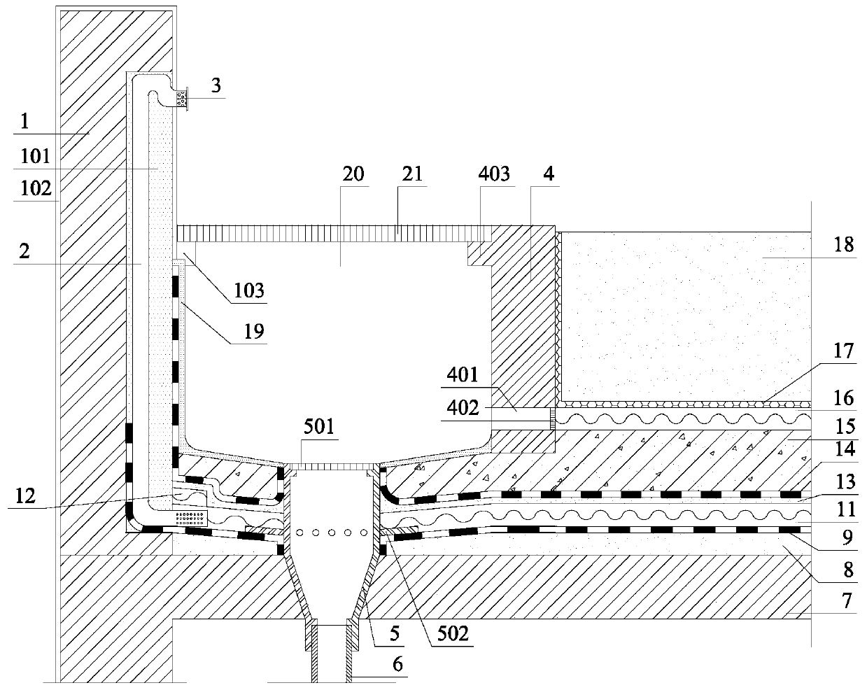
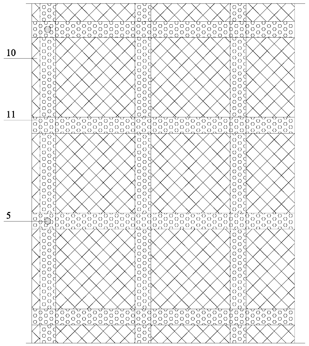
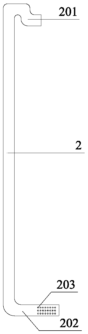
[0036] combined with figure 1 As shown, the invisible natural ventilation and drainage system of the heat preservation and heat insulation planting roof of the present invention includes a parapet 1, a ventilation pipe 2, an air duct 11, a rain bucket 5, a prefabricated retaining wall 4, a roof panel 7, a slope layer A8, a waterproof Layer A9, thermal insulation layer 10, additional ventilation channel 12, slope finding layer B13, waterproof layer B14, rigid protection layer 15, drainage and storage layer 16, filter layer 17, planting soil layer 18, mortar protection layer 19, drainage ditch 20; The ventilation pipe 2 is installed in the parapet 1, and the L-shaped elbow 202 is partly installed in the air duct 11. An additional air duct 1...


PUM


Abstract

The invention relates to a construction method of an invisible natural ventilation and drainage system for a thermal insulation planting roof. The construction method includes the main construction steps of grooving of a parapet wall, construction of a slope making layer A, construction of a waterproof layer A, construction of a thermal insulation layer and an air passage, installation of a ventilation pipe, construction of a waterproof layer B, construction of a rigid protective layer, construction of a planting area and construction of a decoration layer. According to the construction method, a ventilation duct is arranged in a cross grid shape in the thermal insulation layer; then, a conduit is installed circumferentially on the outer side of a rainwater hopper, and the conduit extendsinto the ventilation duct to form an invisible drainage system; the ventilation pipe is further installed in a grooving opening of the parapet wall, and a L-shaped elbow extends into the ventilation duct to form an invisible natural ventilation system; and after the construction of each structural layer of the roof is completed, the parapet wall decoration layer is constructed, and a ventilation pipe cover is installed in a S-shaped elbow. The ventilation and drainage system is reasonable in structure, easy to construct, high in drainage and waterproof performance, and good in exhaust and ventilation effect.

Description

technical field [0001] The invention relates to an invisible natural ventilation and drainage system for thermal insulation and planting roofs, which belongs to the field of construction engineering and is suitable for the construction of roof ventilation and drainage systems, especially for the construction of planting roof ventilation and drainage systems. Background technique [0002] The planted roof not only has good heat insulation in summer and thermal stability in winter, but also has a good effect on reducing the urban heat island effect, purifying the air, and beautifying the living environment. However, compared with the traditional roof, the planted roof has more planting soil layer, water filtration and drainage system, which puts forward new requirements for the performance of the roof structure such as waterproof, drainage, exhaust, crack resistance and puncture resistance. There are many deficiencies in the traditional planted roof ventilation and drainage sy...

Claims


Application Information

Patent Timeline
Patent Type & Authority Applications(China)
IPC IPC(8): E04D13/04E04D13/16E04D13/17
CPCE04D13/0409E04D13/1681E04D13/172
Inventor 陈小林朱凯
Owner 杭州昂创科技有限公司
Why Eureka
Try Eureka