Time difference ranging radar structure with low power consumption and simple structure

A ranging radar technology with simple structure, applied in the field of time difference ranging radar structure, can solve problems such as difficulty in reaching very high bandwidth, limiting ranging resolution, etc., achieving low center frequency and bandwidth requirements, simple structure, and reduced power consumption Effect

Inactive Publication Date: 2020-07-17
BEIJING INSTITUTE OF TECHNOLOGYGY
View PDF6 Cites 2 Cited by
  • Summary
  • Abstract
  • Description
  • Claims
  • Application Information

AI Technical Summary

Problems solved by technology

[0006] It can be seen from formula (2) that the resolution of traditional frequency difference ranging is affected by the system bandwidth, and for many radar system...

Method used


Image

  • Time difference ranging radar structure with low power consumption and simple structure
  • Time difference ranging radar structure with low power consumption and simple structure
  • Time difference ranging radar structure with low power consumption and simple structure

Examples


Embodiment 1

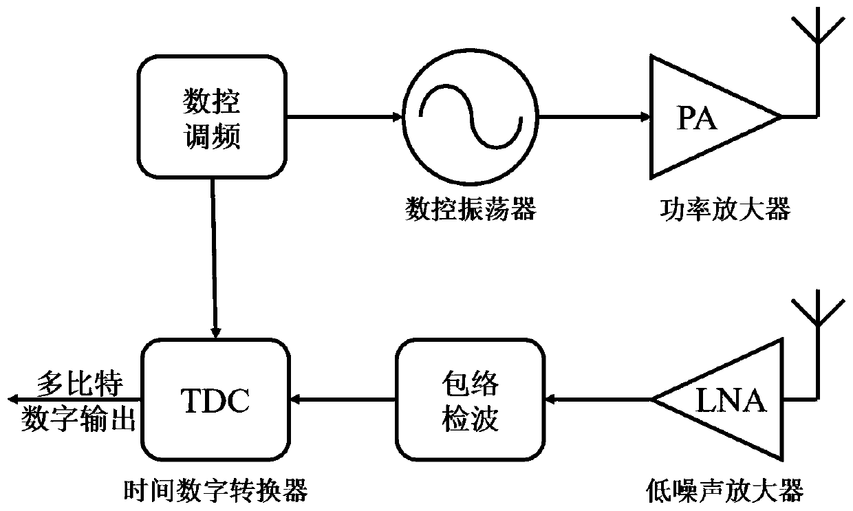
[0057] The system block diagram of the time difference ranging radar structure is as follows figure 1 As shown, it mainly includes digital gradient generator DGG, digital control oscillator DCO, power amplifier PA, transmitting antenna, receiving antenna, low noise amplifier LNA, envelope detector, time-to-digital converter TDC;

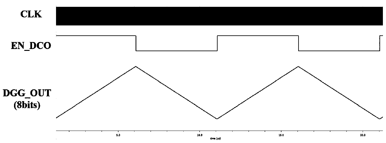
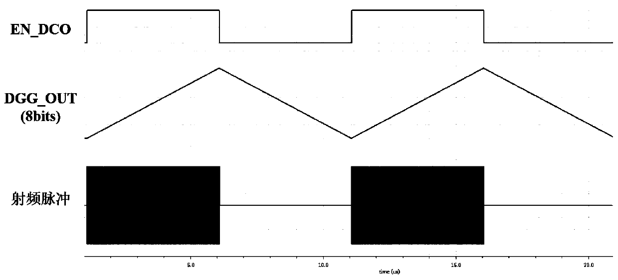
[0058] Among them, the function of the digital gradient generator is to add and subtract the counter with a certain time step under the control of a relatively low-frequency clock, and generate step-like multi-bit digital signals with alternating upward and downward gradients; simultaneously generate A digital square wave signal with a logic high level when going up the gradient and a logic low level when going down the gradient is used as the enable signal of the digitally controlled oscillator;

[0059] Among them, the function of the digital control oscillator is to perform frequency modulation under the control of the enable signal, and frequency...


PUM


Abstract

The invention relates to a time difference ranging radar structure with low power consumption and simple structure, and belongs to the technical field of radar structures and radar ranging. The structure comprises a digital gradient generator, a digital control type oscillator, a power amplifier, a transmitting and receiving antenna, a low-noise amplifier, an envelope detector and a time-to-digital converter. The time difference ranging radar structure can solve the problem that the radar resolution of a frequency modulated continuous wave radar is seriously limited by bandwidth, meanwhile, anoscillator in a transmitter part is controlled by an enable signal, and when a multi-bit digital signal is input, the oscillator only works in a half cycle that the multi-bit digital signal is in anupward gradient, so that the power consumption is greatly reduced; in the receiver part, the demodulation and measurement circuit part adopts an envelope detector to detect the envelope of an echo signal, and adopts a time-to-digital converter to measure the time difference, so that compared with a coherent demodulation and frequency difference measurement method of a frequency-modulated continuous wave radar, the structure is simple.

Description

technical field [0001] The invention relates to a time-difference ranging radar structure with low power consumption and simple structure, and the radar belongs to the technical field of radar structure and radar ranging. Background technique [0002] The traditional frequency-modulated continuous wave radar transmits a series of frequency-modulated continuous waves, and receives the echo signal from the target, also known as the received signal, and coherently mixes the transmitted signal and the received signal to obtain a signal containing target distance information. The distance information is converted into a frequency difference, and then the frequency difference is used for ranging. The traditional FM continuous wave radar uses the frequency difference ranging method, and the formula for calculating the distance between the radar and the target is: [0003] [0004] Among them, c is the speed of light, T s It is half of the period of the transmitted signal, and ...

Claims


Application Information

Patent Timeline
IPC IPC(8): G01S13/32
CPCG01S13/32
Inventor 周波金烨然李尧
Owner BEIJING INSTITUTE OF TECHNOLOGYGY
Why Eureka
Try Eureka