
Energy conversion device having low-temperature coil

An energy conversion device and low-temperature coil technology, which is applied in the field of electromagnet excitation, can solve the problems of large thermal power, large refrigerator capacity, and large heat generation of current leads, and achieve overall weight reduction, high operating current, and heat reduction. Effect

Inactive Publication Date: 2020-07-17
SHANGHAI JIAOTONG UNIV
View PDF6 Cites 0 Cited by
  • Summary
  • Abstract
  • Description
  • Claims
  • Application Information

AI Technical Summary

Problems solved by technology

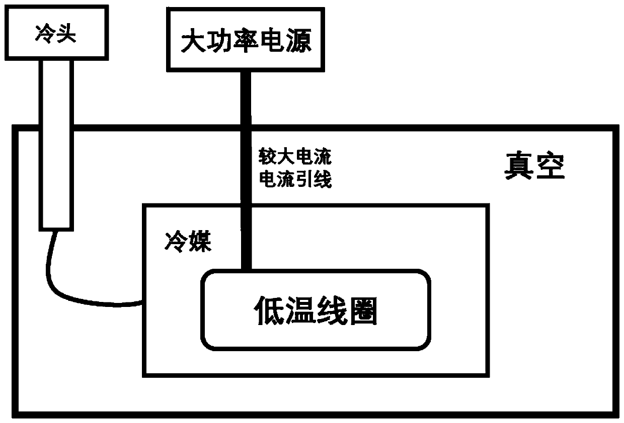
[0012] (1) It solves the problems that the existing low-temperature coil open-loop excitation technology (prior art 1) has a large amount of heat generated by the current lead, which leads to a large capacity of the refrigerator required, and the coil low-temperature system is too bulky, etc.
Open-loop operation can avoid the dependence on the harsh manufacturing process of ultra-low resistance or non-resistance joints during closed-loop operation; it solves the low utilization rate of superconducting materials (the closed-loop operating current of superconducting coils is relatively lower than that of open-loop under the same conditions); For closed coils wound with high-temperature superconducting materials (such as REBCO, etc.), it is not easy to quickly release energy, etc.
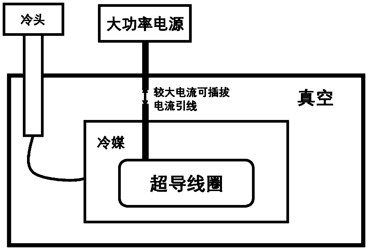
[0013] (2) It solves the problem that the excitation system existing in the existing superconducting coil closed-loop excitation technology (prior art 2) is relatively complex; during excitation, the heat generated by the current leads is still relatively large, and the traditional pluggable current leads have connections Problems such as large thermal power caused by interface contact thermal resistance

Method used


Image

  • Energy conversion device having low-temperature coil
  • Energy conversion device having low-temperature coil
  • Energy conversion device having low-temperature coil

Examples


Embodiment Construction

[0085] The following describes several preferred embodiments of the present invention with reference to the accompanying drawings, so as to make the technical content clearer and easier to understand. The present invention can be embodied in many different forms of embodiments, and the protection scope of the present invention is not limited to the embodiments mentioned herein.

[0086] In the drawings, components with the same structure are represented by the same numerals, and components with similar structures or functions are represented by similar numerals or letters. The size and thickness of each component shown in the drawings are shown arbitrarily, and the present invention does not limit the size and thickness of each component. In order to make the illustration clearer, the thickness of parts is appropriately exaggerated in some places in the drawings.

[0087] The relevant concepts described in this application document are defined as follows:

[0088] Cryogenic ...


PUM


Abstract

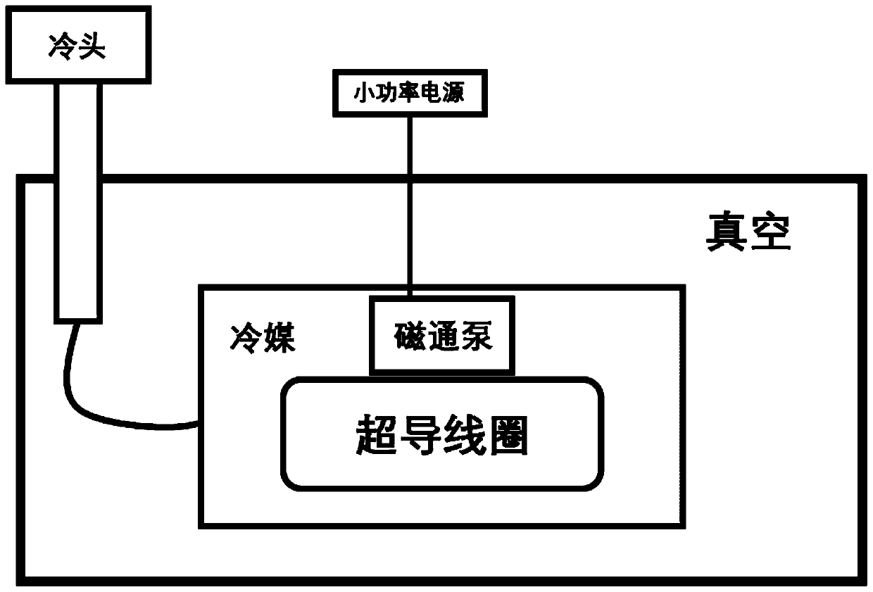
The invention discloses an energy conversion device with a low-temperature coil, and relates to the technical field of electromagnet excitation. The energy conversion device comprises a cold source module, a vacuum module, an external energy module, an internal energy module and a connecting module, wherein the cold source module is configured to provide a cold source for the vacuum module, the external energy module is configured to be located outside the vacuum module, the internal energy module is configured to be located inside the vacuum module, and the internal energy module and the external energy module are configured to be connected through the connecting module. The energy conversion device with the low-temperature coil further comprises a refrigerant module, the refrigerant module is configured to be located in the vacuum module, and the internal energy module is configured to be located in the refrigerant module. The connection module comprises a power electronic converter,the power electronic converter comprises a large current unit and a small current unit, the small current unit is configured to be located outside the vacuum module, and the large current unit is connected with the internal energy module through a large current lead.

Description

technical field [0001] The invention relates to the technical field of electromagnet excitation, in particular to an energy conversion device with a low-temperature coil. Background technique [0002] The phenomenon of superconductivity was discovered in 1911, and due to its excellent properties such as zero resistance, it quickly attracted the attention of researchers all over the world. The critical temperature of superconducting materials can reach 20K-77K or even higher, and some materials can enter the superconducting state in the liquid nitrogen environment. At present, some superconducting materials have achieved industrial mass production (such as NbTi, Ni 3 Sn, MgB 2 , ReBCO, etc.), due to its zero-resistance characteristics, the superconducting coil made of superconducting material can produce a magnetic induction intensity that cannot be achieved compared with the coil made of traditional copper wire under DC excitation, and in a certain In some occasions, unde...

Claims


Application Information

Patent Timeline
Patent Type & Authority Applications(China)
IPC IPC(8): H02M3/158H05K7/20
CPCH02J50/10H01F6/008H02M3/33584H02M7/5387H05K7/20H02M3/158H01F6/06H02M1/007H02M3/156H02M3/33507H02M7/003H02M5/4585H02M3/1582H01F6/04Y02E40/60
Inventor 黄振
Owner SHANGHAI JIAOTONG UNIV
Learn More