Through-hole reflow soldering equipment and machining method

A reflow soldering and reflow soldering machine technology, applied in welding equipment, metal processing equipment, manufacturing tools, etc., can solve the problems of waste of resources, increase of artificial plug-ins and wave soldering processes, and high temperature resistance of components, to prevent high temperature damage. Effect

Active Publication Date: 2020-07-28
金升阳(怀化)科技有限公司
View PDF7 Cites 3 Cited by
  • Summary
  • Abstract
  • Description
  • Claims
  • Application Information

AI Technical Summary

Problems solved by technology

There are some defects in the technology of using "wave soldering" soldering: 1. Wave soldering needs to spray flux first, and then go through preheating, welding, and cooling area. There are many flux residues, and cleaning processes need to be added later; 2. During wave contact, the temperature of all components will rise, requiring all components to be resistant to high temperatures; 3. When used in the SMT red glue process, there should be no SMT solder paste components on the wave-passing surface; 4. High soldering failure and high void rate , the latter part requires a lot of manual inspection and repair welding; 5. The waste of resources is serious, and a large amount of tin strips and flux are required to be consumed
There are certain defects in the "ordinary reflow soldering" currently on the market: 1. It needs to go through preheating, reflow, and cooling zones. The isolation of hot air, the temperature of the upper and lower furnace chambers is the same, and there is no temperature difference, so the temperature resistance of components is required to be high; 2. The welding defect is high, the void rate is high, and the product has a lot of false soldering; 3. The PCB board needs double-sided welding. , there must be a "wave soldering" process, which increases labor costs and the risk of poor soldering
Therefore, the existing process adds manual plug-in and wave soldering processes, and a lot of manpower is invested

Method used


Image

  • Through-hole reflow soldering equipment and machining method
  • Through-hole reflow soldering equipment and machining method
  • Through-hole reflow soldering equipment and machining method

Examples


Embodiment Construction

[0061] In order to make those skilled in the art better understand the technical solution of the present invention, the technical solution of the present invention will be described in detail below with reference to the drawings and specific embodiments, but the embodiments of the present invention are not limited thereto.

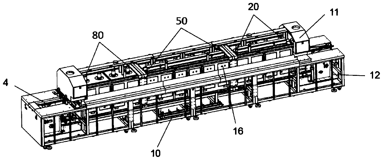
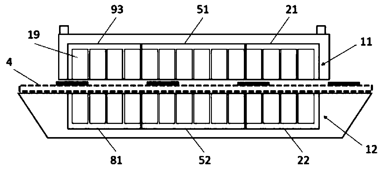
[0062] Such as figure 1 , figure 2 , image 3 , Figure 4 , Figure 5 , Image 6 , Figure 7 , Figure 8 , Figure 9 , Figure 10 , Figure 11 with Figure 12 Shown is the overall and partial structural view of the through-hole reflow soldering equipment of the present invention.

[0063] Such as Figures 1 to 4 As shown, it is a structural diagram of the through-hole reflow soldering equipment of the present invention. A through-hole reflow soldering equipment includes a through-hole reflow soldering machine 1, and the machine 1 is respectively set into three temperature zones along the horizontal direction, that is, the first Temperature zon...


PUM


Abstract

The invention discloses through-hole reflow soldering equipment. The equipment comprises a machine platform; the machine platform comprises three temperature zones including a first temperature zone,a second temperature zone and a third temperature zone in the horizontal direction; each temperature zone is separated into an upper furnace cavity and a lower furnace cavity along a conveying track in the vertical direction; a heat insulation device is arranged between the upper furnace cavity and the lower furnace cavity of each temperature zone and is used for stopping air flowing of the lowerfurnace cavity and the upper furnace cavity; the upper furnace cavity of the first temperature zone delivers room-temperature air, and the lower furnace cavity delivers low-temperature hot air; the upper furnace cavity of the second temperature zone delivers cold air treated by a condensing system, and the lower furnace cavity delivers high-temperature hot air; and the upper furnace cavity of thethird temperature zone delivers the cold air treated by the condensing system, and the lower furnace cavity delivers the room-temperature air. The equipment is applicable to the PCB through hole soldering technology, the temperature difference of the upper and lower furnace cavities is ensured to be in the control range, and the soldering effect is better.

Description

technical field [0001] The invention relates to a welding process of a circuit board or a PCB board, in particular to a through-hole reflow soldering equipment and a through-hole reflow soldering processing method. [0002] technical background [0003] At present, in the soldering technology of PCB boards, there are mainly two types of equipment: "ordinary reflow soldering" and "wave soldering". "Wave soldering" is a tin bath that melts a tin bar into a liquid state, and uses the agitation of the motor to form a wave crest. The PCB board passes through the tin wave crest, so that the product components and pads are welded together. It is mainly used for plug-in components and SMT red glue craft. There are some defects in the technology of using "wave soldering" soldering: 1. Wave soldering needs to spray flux first, and then go through preheating, welding, and cooling area. There are many flux residues, and cleaning processes need to be added later; 2. During wave contact,...

Claims


Application Information

Patent Timeline
Patent Type & Authority Applications(China)
IPC IPC(8): B23K1/008B23K1/08B23K3/03H05K3/34H05K13/04
CPCB23K1/008B23K1/08B23K3/03H05K3/34H05K3/341H05K13/0465
Inventor 曾志威龙建成钟为雪
Owner 金升阳(怀化)科技有限公司
Why Eureka
Try Eureka