Control system and working method of computer panel saw

A computer panel saw and control system technology, which is applied to work accessories, manufacturing tools, wood processing appliances, etc., and can solve problems such as no disclosure of system components.

Pending Publication Date: 2020-07-28
NANXING MACHINERY CO LTD
View PDF4 Cites 5 Cited by
  • Summary
  • Abstract
  • Description
  • Claims
  • Application Information

AI Technical Summary

Problems solved by technology

The patent does not disclose the specific system co

Method used


Image

  • Control system and working method of computer panel saw
  • Control system and working method of computer panel saw
  • Control system and working method of computer panel saw

Examples


Embodiment 1

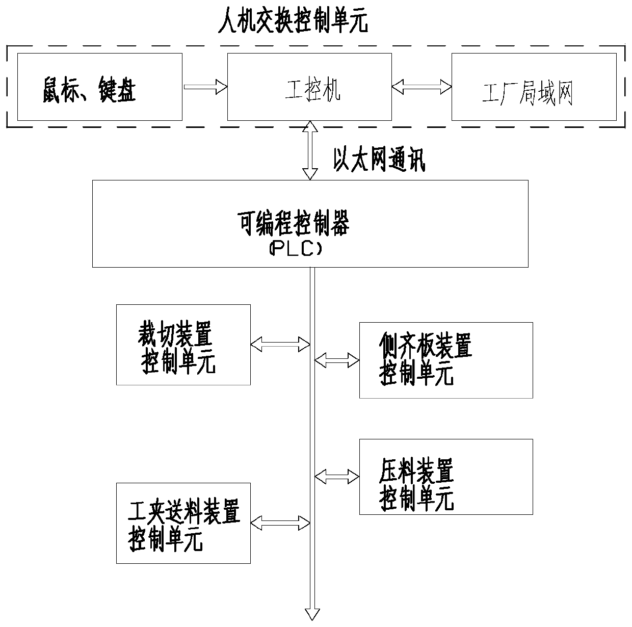
[0108] Such as figure 1 As shown, a control system of a computerized panel saw includes a man-machine exchange control unit, a programmable controller (PLC) connected to the man-machine exchange control unit through Ethernet for two-way control, and a data bus connected to the programmable controller , Two-way control in parallel connected to the data bus clamp feeding device control unit, side alignment device control unit, pressing device control unit, cutting device control unit.

[0109] The human-machine exchange control unit includes an industrial computer, a mouse and a keyboard connected to the industrial computer for one-way control, and a factory LAN connected to the industrial computer for two-way control; the mouse and keyboard one-way control the industrial computer. The industrial computer is connected with the programmable controller bidirectionally through Ethernet.

[0110] Programmable logic controller (PLC) refers to the program control system of computer n...

Embodiment 2

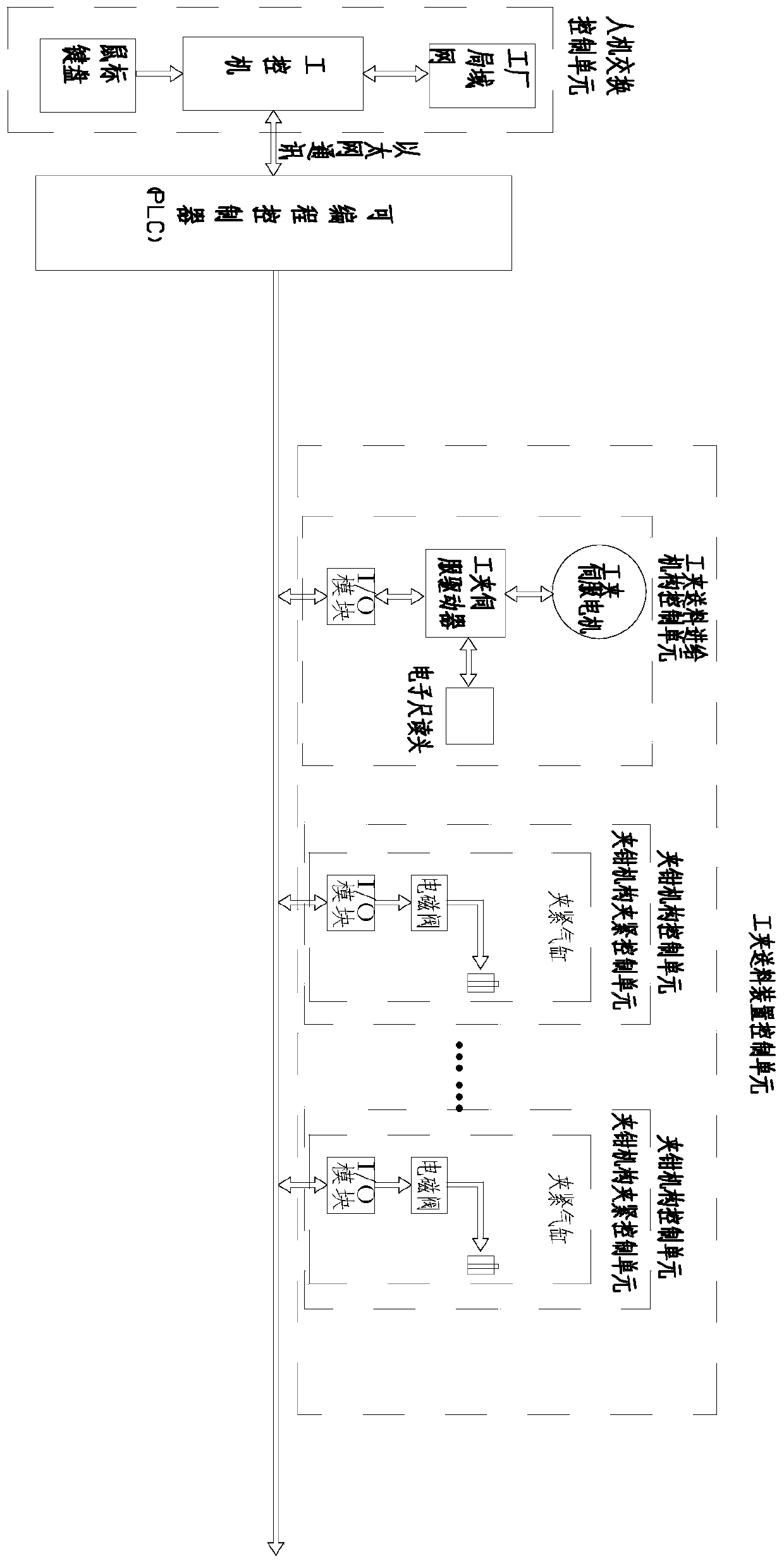
[0137] Such as Figure 4 As shown, the difference from Embodiment 1 is that the computerized panel saw also includes a feeding device control unit, a pushing device control unit, and a front aligning device control unit

[0138] Such as Figure 5 As shown, the feeding device control unit includes a feeding device feeding control unit and a feeding device feeding control unit.

[0139] The feeding control unit of the feeding device includes an I / O module connected in parallel with the bidirectional control of the data bus, a thermal relay connected in series with the one-way control of the I / O module, a contactor connected in series with the one-way control of the thermal relay, and a contactor connected in series with the one-way control of the I / O module. One-way control of the feed motor connected in series; I / O module one-way control of the thermal relay, one-way control of the thermal relay contactor, one-way control of the contactor feed motor.

[0140]The feeding contr...

Embodiment 3

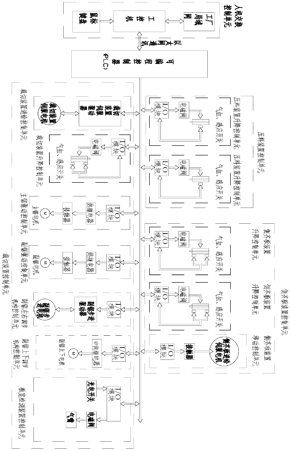
[0147] Such as Figure 6 As shown, the difference from Embodiment 2 is that the feeding device control unit includes a feeding device feeding control unit and a feeding device feeding control unit.

[0148] The feeding control unit of the feeding device includes an I / O module connected in parallel with the bidirectional control of the data bus, a thermal relay connected in series with the one-way control of the I / O module, a contactor connected in series with the one-way control of the thermal relay, and a contactor connected in series with the one-way control of the I / O module. One-way control of the feed motor connected in series; I / O module one-way control of the thermal relay, one-way control of the thermal relay contactor, one-way control of the contactor feed motor.

[0149] The feeding control unit of the feeding device includes an I / O module connected in parallel with the bidirectional control of the data bus, a thermal relay connected in series with the unidirectional...


PUM


Abstract

The invention relates to a control system and working method of a computer panel saw. The computer panel saw comprises a programmable logic controller (PLC), a data bus, a work clamp feeding device control unit, a pressing device control unit and a cutting device control unit. The data bus is connected with the PLC. The work clamp feeding device control unit, the pressing device control unit and the cutting device control unit are connected in parallel with the data bus in a bidirectional control mode. The work clamp feeding device control unit comprises a work clamp feeding mechanism controlunit and a plurality of clamp mechanism control units. The pressing device control unit comprises two pressing device lifting control units. The cutting device control unit comprises a cutting devicefeeding control unit, a cutting device lifting control unit, a main saw drive control unit, an auxiliary saw drive control unit, and a board width detection device control unit. The computer panel sawhas the advantages of high safety, fault tolerance, high efficiency, stability, high precision and simple control structure.

Description

technical field [0001] The present invention relates to a cutting and processing equipment for wood-based panels (including density boards, particle boards, multi-layer boards, etc.) The control system and working method of the computerized panel saw. Background technique [0002] The components for producing panel furniture are generally rectangular panels, which are assembled by sawing large panels of wood into small pieces. Computerized panel saw is a kind of cutting equipment for wood-based panels and their analogues, which is mainly used in the production process of panel furniture. [0003] In the utility model with the patent number 201720226821.6 and the public announcement date being November 10, 2017, a high-speed computerized panel saw is disclosed, including a machine table, a controller installed on the machine table, a feeding device installed on the machine table, A pressing device for pressing the sheet to be sawed, a saw car for sawing the sheet and a disc...

Claims


Application Information

Patent Timeline
IPC IPC(8): B27C9/00B28D7/00
CPCB27C9/00B28D7/005
Inventor 郭飞肖志群郭朝元曹梦莲秦振伟梁浩伟
Owner NANXING MACHINERY CO LTD
Why Eureka
Try Eureka