Vortex light-based micro-vibration detection device for constant-rotating-speed rotating object

A detection device and constant speed technology, applied in measuring devices, measuring ultrasonic/sonic/infrasonic waves, instruments, etc., can solve problems such as difficult measurement and frequency change, and achieve the effects of easy control, rapid response and high sensitivity

Active Publication Date: 2020-07-28
PLA PEOPLES LIBERATION ARMY OF CHINA STRATEGIC SUPPORT FORCE AEROSPACE ENG UNIV
View PDF7 Cites 8 Cited by
  • Summary
  • Abstract
  • Description
  • Claims
  • Application Information

AI Technical Summary

Problems solved by technology

This phenomenon still exists in the frequency range of visible light, but due to the high frequency of light, it is difficult to measure the frequency change once the speed is large

Method used


Image

  • Vortex light-based micro-vibration detection device for constant-rotating-speed rotating object
  • Vortex light-based micro-vibration detection device for constant-rotating-speed rotating object
  • Vortex light-based micro-vibration detection device for constant-rotating-speed rotating object

Examples


Embodiment Construction

[0038] specific implementation plan

[0039] In the present invention, the superposition vortex beam is used as the detection carrier, and the specific implementation steps are as follows:

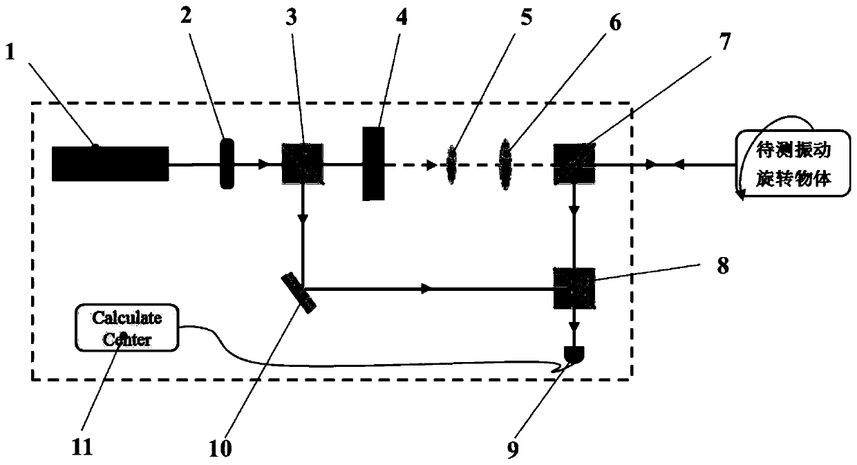
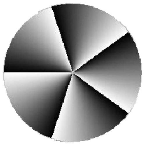
[0040] First, the laser (1) generates a laser beam with a wavelength of 632.8nm, which becomes horizontally polarized light after passing through the polarizer (2), and then is divided into two beams by the beam splitter (3), and one beam is used as the detection light and projected on the spiral phase plate ( 4), another beam is directed to the plane reflector (10) as local oscillation light, and the basic structure of the spiral phase plate is as follows figure 2 shown.

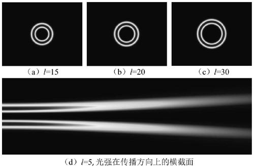
[0041] The light beam passing through the spiral phase plate (4) becomes a vortex light with a specific topological charge. The lens groups (5) and (6) expand and collimate the vortex beam, and then pass through the beam splitting prism (7) to irradiate to For the rotating object to be tested, the light beam reflecte...


PUM


Abstract

The invention relates to a vortex light-based micro-vibration detection device for a constant-rotating-speed rotating object. The device mainly comprises a laser, a polarizing film, a beam splitter prism, a spiral phase plate, a convex lens group, a plane mirror, a photoelectric detector and a miniature oscilloscope. Firstly, a laser light source and the spiral phase plate are combined to generatean annular vortex light beam, and the vortex light beam is expanded and collimated by the lens group and then irradiates the surface of a to-be-measured object; secondly, a light beam scattered backfrom the surface of the object and a reference light beam split by the laser are subjected to convergence frequency beating through the beam splitter prism; finally, the photoelectric detector detectslight intensity information of the mixed light beam and inputting the light intensity information into the oscilloscope for spectral analysis. Whether the rotating object vibrates slightly or not andthe vibration frequency of the rotating object can be observed according to the change condition of the frequency shift signal displayed by the oscilloscope. The device is simple in structure, and particularly has high sensitivity for tiny vibration.

Description

technical field [0001] The invention mainly relates to the fields of optics, physics, photoelectric conversion, and signal detection, especially technical methods such as phase modulation and beat frequency detection of light beams. [0002] technical background [0003] The technical background of the present invention is mainly based on the optical Doppler effect. The Doppler effect can be traced back to 1842, and since its discovery, it has been used in many aspects of our lives today. His basic principle is that when the wave source moves in the opposite direction relative to the receiving device, the frequency of the wave received by the receiver will increase; when the wave source moves in the opposite direction relative to the receiving device, the frequency received by the receiver will decrease. The greater the relative motion speed, the greater the received frequency change. [0004] The Doppler effect is ubiquitous in all kinds of waveforms. In sound waves, when ...

Claims


Application Information

Patent Timeline
Patent Type & Authority Applications(China)
IPC IPC(8): G01H9/00
CPCG01H9/00
Inventor 任元邱松刘通李晋川王琛李智猛陈琳琳陈晓岑丁友沙启蒙
Owner PLA PEOPLES LIBERATION ARMY OF CHINA STRATEGIC SUPPORT FORCE AEROSPACE ENG UNIV
Why Eureka
Try Eureka