Eureka AIR delivers breakthrough ideas for toughest innovation challenges, trusted by R&D personnel around the world.

Manufacturing method of radial strengthening sliding bearing static ring

A manufacturing method and sliding bearing technology, applied in the field of metal processing and manufacturing, can solve the problems of low working life, high manufacturing cost and unsatisfactory performance of sliding bearings

Active Publication Date: 2020-07-31
BEIJING CHUNLUN PETROLEUM TECH DEV CO LTD
View PDF7 Cites 4 Cited by
  • Summary
  • Abstract
  • Description
  • Claims
  • Application Information

AI Technical Summary

Problems solved by technology

Due to technical confidentiality and economic benefits, domestic research and development units have not been able to communicate with each other on key technologies such as TC bearing molds and manufacturing methods, and there are no relevant literature reports, resulting in a variety of TC bearing molds and manufacturing processes, and a high scrap rate. No less, mainly reflected in: the hardness of the base material of the static ring and the dynamic ring is not up to the hardness HRC32~36 required by the downhole tool parts (usually only HRC25~30); the static ring and the dynamic ring are casted with tungsten carbide and copper base There are impurities in the alloy binder (shown as black holes of different sizes), the bonding strength between the hard alloy wear-resistant material and the cast tungsten carbide is low (≤60MPa), and the working life of the sliding bearing is low; secondly, when there is too much cast tungsten carbide, turning Difficult to process (cannot be processed by turning), high manufacturing cost, low cost performance, and cannot meet the needs of actual drilling downhole tools

Method used


Image

  • Manufacturing method of radial strengthening sliding bearing static ring
  • Manufacturing method of radial strengthening sliding bearing static ring
  • Manufacturing method of radial strengthening sliding bearing static ring

Examples


Embodiment Construction

[0066] In order to enable those skilled in the art to better understand the technical solutions in the present invention, the technical solutions in the embodiments of the present invention will be clearly and completely described below in conjunction with the accompanying drawings in the embodiments of the present invention. Obviously, the described The embodiments are only some of the embodiments of the present invention, not all of the embodiments. Based on the implementation manners in the present invention, all other implementation manners obtained by persons of ordinary skill in the art without making creative efforts shall fall within the protection scope of the present invention.

[0067] It should be noted that when an element is referred to as being “disposed on” another element, it may be directly on the other element or there may also be an intervening element. When an element is referred to as being "connected to" another element, it can be directly connected to t...


PUM

PropertyMeasurementUnit
thicknessaaaaaaaaaa
heightaaaaaaaaaa
thicknessaaaaaaaaaa

Abstract

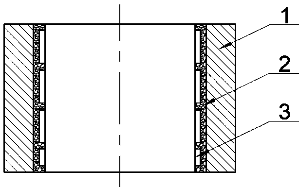
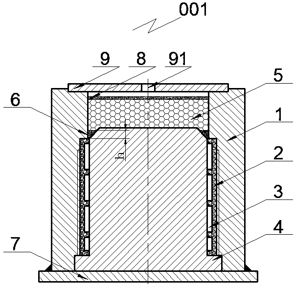
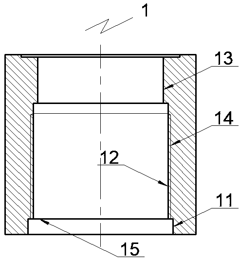
The invention provides a manufacturing method of a radial strengthening sliding bearing static ring. The method comprises the steps that a static ring manufacturing mold is acquired, the mold comprises a core mold and a matrix coaxially placed outside the core mold, annular space is formed between the core mold and the matrix, and containing space is formed among the core mold, the matrix and a cover plate; a locating datum is arranged, a to-be-bonded component is cleaned, and a wear-resisting part is bonded to the outer cylinder face of the core mold; filler is assembled, cast tungsten carbide powder is dumped into the residual clearance of the annular space, locating powder is placed into the position above the cast tungsten carbide powder to form a locating layer, then a certain quantity of a bonding alloy is placed according to the proportion, a certain quantity of a fluxing agent is evenly scattered on the bonding alloy according to the proportion, and the mold is covered with thecover plate; the assembled and filled mold is sintered, and a static ring blank is obtained; and after air cooling, the static ring blank is machined, and the size of the static ring can meet the design requirements. By means of the method, the work life of a radial strengthening sliding bearing can be prolonged, and meanwhile the machining difficulty and manufacturing cost can be reduced.

Description

technical field [0001] The invention relates to the technical field of metal processing and manufacturing of downhole tools for drilling, in particular to a method for manufacturing a static ring of a radially righting sliding bearing of a rotary steerable system. Background technique [0002] Radial righting sliding bearings are vulnerable parts of drilling downhole tools. When maintaining downhole tools, replacing radial righting sliding bearings is one of the main tasks. At present, the radial centralizing sliding bearings of downhole tools are basically radial centralizing carbide sliding bearings (TC bearings for short). The hardness of the alloy is very high (HRA89~92), but because the drilling fluid contains a large amount of solid particles (such as iron ore powder, quartz sand, etc.), these fine particles will affect the static ring and the moving ring of the bearing when passing through the working gap of the centralizing bearing. The wear-resistant materials on t...

Claims


Application Information

Patent Timeline
Patent Type & Authority Applications(China)
IPC IPC(8): B22F3/10B22F5/10C22C32/00
CPCB22F3/1035B22F5/106C22C32/0052
Inventor 赵红梅
Owner BEIJING CHUNLUN PETROLEUM TECH DEV CO LTD
Why Eureka
Eureka Blog
Learn More