Waste tire cracking device and method based on combination of dividing wall heat exchange and microwave heating

A microwave heating device and microwave heating technology are applied in the direction of combined direct and indirect heating dry distillation, special form dry distillation, petroleum industry, etc., which can solve the problems of increased energy consumption, reduced thermal efficiency, large energy loss, etc., and solve the problem of microwave absorption performance Dependence, enhanced heat transfer throughout the process, and enhanced wave-absorbing performance

Inactive Publication Date: 2020-07-31
SOUTHEAST UNIV
View PDF6 Cites 5 Cited by
  • Summary
  • Abstract
  • Description
  • Claims
  • Application Information

AI Technical Summary

Problems solved by technology

[0004] 1. High energy consumption
The microwave heating reactor needs the microwave generator to generate high-frequency electromagnetic waves first, and the energy loss in the electromagnetic conversion process is relatively large
However, microwave heating participates in the whole process of preheating, heating, and cracking of materials, resulting in high energy consumption.
[0005] 2. Higher requirements on the absorbing performance of materials
Microwave heating strongly depends on the microwave absorption of materials. The initial microwave absorption performance of waste tire particles is poor, and the dissipation of microwaves will be greatly enhanced, reducing thermal efficiency.
[0006] 3. It is difficult to realize the continuous processing of materials
In the existing fixed-bed microwave reactor, microwave heating needs to be stopped when adding and collecting materials, which reduces the processing efficiency, and frequent microwave start and stop will also lead to increased energy consumption

Method used


Image

  • Waste tire cracking device and method based on combination of dividing wall heat exchange and microwave heating

Examples


Embodiment Construction

[0028] The present invention will be further described below in conjunction with the accompanying drawings.

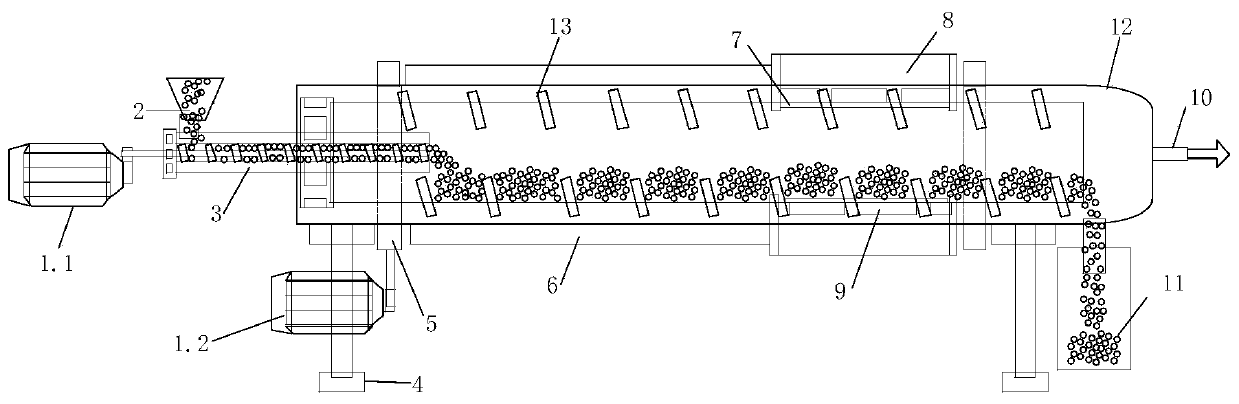
[0029] like figure 1 Shown is a waste tire cracking device based on the combination of partition heat exchange and microwave heating. The main body of the cracking device is a horizontal cylindrical shell 12, and a screw conveying device 3 is arranged on the left side of the shell 12. The screw conveying device 3 The right half is located in the housing 12, and the upper left side of the screw conveying device 3 is provided with a feed inlet 2, and the screw conveying device 3 is driven by the first speed-regulating motor 1.1, and a heating element is provided at the lower right side of the housing 12. The carbon black collection box 11 is decomposed, and the electric heating device 6 is installed on the front section outside the housing 12. The microwave heating device 9 of the microwave heating section is installed on the rear section outside the housing 12. There ar...


PUM


Abstract

The invention discloses a waste tire cracking device and method based on combination of dividing wall heat exchange and microwave heating. The main body of the cracking device is a horizontal cylindrical shell (12); a spiral conveying device (3) is arranged on the left side of the shell; the right half section of the spiral conveying device is positioned in the shell; a feeding opening (2) is arranged in the upper part of the left side of the spiral conveying device; the spiral conveying device is driven by a first speed regulating motor (1.1); a pyrolytic carbon black collecting box (11) is arranged at the lower end of the right side of the shell, an electric heating device (6) is installed on the front section outside the shell, a microwave heating device (9) of a microwave heating section is installed on the rear section outside the shell, four supporting frames (4) are arranged on the lower portion of the shell to support the whole device, and spiral blades (13) are arranged in theshell and penetrate through the shell from left to right. The spiral structure is used for conveying materials, so that the material adaptability of the reactor is improved; and the waste tire particles are slightly carbonized in the continuous temperature rising process of front-section electric heating, so that the wave absorbing property of the waste tire particles is greatly improved.

Description

technical field [0001] The invention provides a waste tire pyrolysis device based on the combination of partition wall heat exchange and microwave heating, which belongs to the technical field of solid waste reuse. Background technique [0002] Waste tires have a high energy density and a large output growth rate, but unreasonable use will pollute the environment. Pyrolysis of waste tires is a very potential comprehensive and resource utilization technology. The traditional heating method will lead to low pyrolysis efficiency of waste tires, mainly because tires are poor conductors of heat and the thermal resistance of tire particles is relatively large. Therefore, a larger residence time is required to meet the cracking requirements. Therefore, under the traditional heating method, the length and volume of the reactor become very large. In order to reduce the main body length of the reactor, microwave heating is widely used as a new heating method. Microwave refers to ele...

Claims


Application Information

Patent Timeline
Patent Type & Authority Applications(China)
IPC IPC(8): C10B53/07C10B51/00
CPCC10B51/00C10B53/07Y02P20/143
Inventor 肖睿郑宏彬曾德望王兵
Owner SOUTHEAST UNIV
Why Eureka
Try Eureka