Tubular parallel flow type gas-liquid contact absorber

A gas-liquid contact and absorber technology, which is applied in gas fuel, chemical instruments and methods, petroleum industry, etc., can solve the problems of poor particle size uniformity, low efficiency and large atomization pressure difference of atomized micro-droplets. Achieve the effect of high gas-liquid mass transfer efficiency, wide adaptability and large processing capacity

Active Publication Date: 2020-07-31
BEIJING INSTITUTE OF PETROCHEMICAL TECHNOLOGY
View PDF15 Cites 8 Cited by
  • Summary
  • Abstract
  • Description
  • Claims
  • Application Information

AI Technical Summary

Problems solved by technology

[0007] Through the above analysis, although the tubular gas-liquid contact absorber has been applied to the field of natural gas purification and has obvious technical advantages in the development of offshore oil and gas fields, the structure of the currently proposed tubular gas-liquid co-current cont...

Method used


Image

  • Tubular parallel flow type gas-liquid contact absorber
  • Tubular parallel flow type gas-liquid contact absorber
  • Tubular parallel flow type gas-liquid contact absorber

Examples


specific Embodiment approach

[0025] The preferred embodiment of the tubular parallel-flow gas-liquid contact absorber of the present invention is:

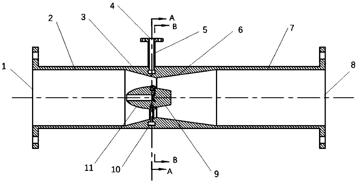
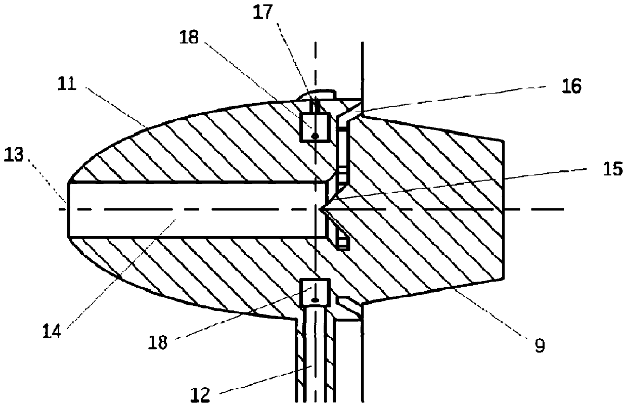
[0026] From the perspective of functional division, it mainly includes a gas steady flow straight pipe section, a gas shrinkage acceleration section, a gas dispersion expansion section, and a gas-liquid uniform mixing mass transfer absorption section connected in sequence. The gas shrinkage acceleration section and the gas dispersion expansion section are equipped with liquid absorption. The agent is injected into the atomization part, and the liquid absorbent injection atomization part includes a built-in ellipsoidal diversion cone and a trapezoidal cone;

[0027] The gas steady flow straight pipe section is a straight pipe from the absorber inlet to the gas shrinkage acceleration section;

[0028] The structure of the gas shrinkage acceleration section is a gas channel with a tapered flow area composed of an inner cone with a tapered diameter and an outer w...

specific Embodiment

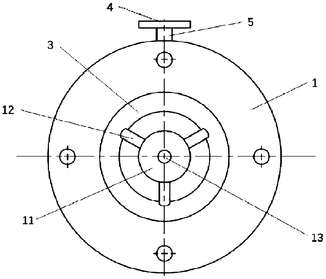
[0048] Such as Figure 1 to Figure 5 As shown, the embodiment of the present invention provides a tubular co-current gas-liquid contact absorber. The outer tube of the contact absorber includes the gas inlet 1 of the absorber, the gas steady flow straight pipe section 2, and the inner cone 3 with tapered diameter. , inner cone 6 with gradually expanding diameter and gas-liquid mixed mass transfer straight pipe section 7. The tubular parallel-flow gas-liquid contact absorber is connected to the gas upstream process pipeline by means of flanges or welding, the gas inlet 1 of the tubular parallel-flow gas-liquid contact absorber is connected to the inner cone 3 with tapered diameter of the outer pipe The circular pipe part between is the gas steady flow straight pipe section 2, and the gas steady flow straight pipe section 2 is connected with the gas shrinkage acceleration section, and the gas shrinkage acceleration section is the inner wall of the outer pipe diameter tapered inn...


PUM


Abstract

The invention discloses a tubular parallel flow type gas-liquid contact absorber which comprises a gas steady flow straight pipe section, a gas contraction acceleration section, a gas dispersion expansion section and a gas-liquid uniform mixing mass transfer absorption section which are connected in sequence; liquid absorbent injection atomization parts are arranged in the gas contraction acceleration section and the gas dispersion expansion section; each of the liquid absorbent injection atomization parts comprises a built-in ellipsoidal flow guide cone and a trapezoidal cone, a flow guide cone liquid annular flow channel is arranged in the ellipsoidal flow guide cone, an outer pipe liquid annular flow channel is communicated with the flow guide cone liquid annular flow channel through aplurality of liquid annular flow channel connecting pipes, and a plurality of liquid incident small holes are evenly distributed in the outer wall face of the flow guide cone liquid annular flow channel in the circumferential direction, an auxiliary atomized gas flow channel is axially arranged in the ellipsoidal flow guide cone, and an auxiliary atomized gas circular seam is formed in the end face of the tail portion of the ellipsoidal flow guide cone. Purification treatment of natural gas dehydration and deacidification under different working conditions can be achieved, the gas-liquid masstransfer efficiency is high, the structure is compact, the treatment amount is large, operation is easy, and the gas-liquid flow application range is wide. The device is especially suitable for an offshore platform to replace a traditional absorption tower in a natural gas dehydration or deacidification process.

Description

technical field [0001] The invention relates to natural gas purification treatment equipment in the process of oil and gas exploitation, in particular to a tubular parallel-flow gas-liquid contact absorber for removing gaseous water and acid gas. Background technique [0002] As we all know, the natural gas extracted from the formation inevitably contains impurities such as water, dust particles, natural gas and hydrogen sulfide. On the one hand, acid gases such as carbon dioxide and hydrogen sulfide contained in natural gas will not only reduce the combustion calorific value of natural gas, but also corrode natural gas pipelines and equipment. On the other hand, the gaseous water (or gas phase water) contained in natural gas will be precipitated as liquid water when the pressure increases or the temperature decreases. These liquid waters will not only combine with some low molecular weight hydrocarbons to form hydrates and cause pipeline Blockage or equipment damage, and w...

Claims


Application Information

Patent Timeline
IPC IPC(8): C10L3/10B01D53/18B01D53/14
CPCB01D53/1456B01D53/18C10L3/102C10L3/106
Inventor 孔令真陈家庆兰天孙欢
Owner BEIJING INSTITUTE OF PETROCHEMICAL TECHNOLOGY
Why Eureka
Try Eureka