Target azimuth imaging method based on superimposed vortex light

An imaging method and target orientation technology, applied in the field of phase and frequency modulation and demodulation, can solve problems such as unrealizable, translation and rotation, and inability to detect beam rotation

Active Publication Date: 2020-07-31
PLA PEOPLES LIBERATION ARMY OF CHINA STRATEGIC SUPPORT FORCE AEROSPACE ENG UNIV
View PDF7 Cites 4 Cited by
  • Summary
  • Abstract
  • Description
  • Claims
  • Application Information

AI Technical Summary

Problems solved by technology

At present, the synthetic aperture cannot realize both translation and rotation, and cannot detect the rotation of the beam in the vertical direction.

Method used


Image

  • Target azimuth imaging method based on superimposed vortex light
  • Target azimuth imaging method based on superimposed vortex light
  • Target azimuth imaging method based on superimposed vortex light

Examples


Embodiment Construction

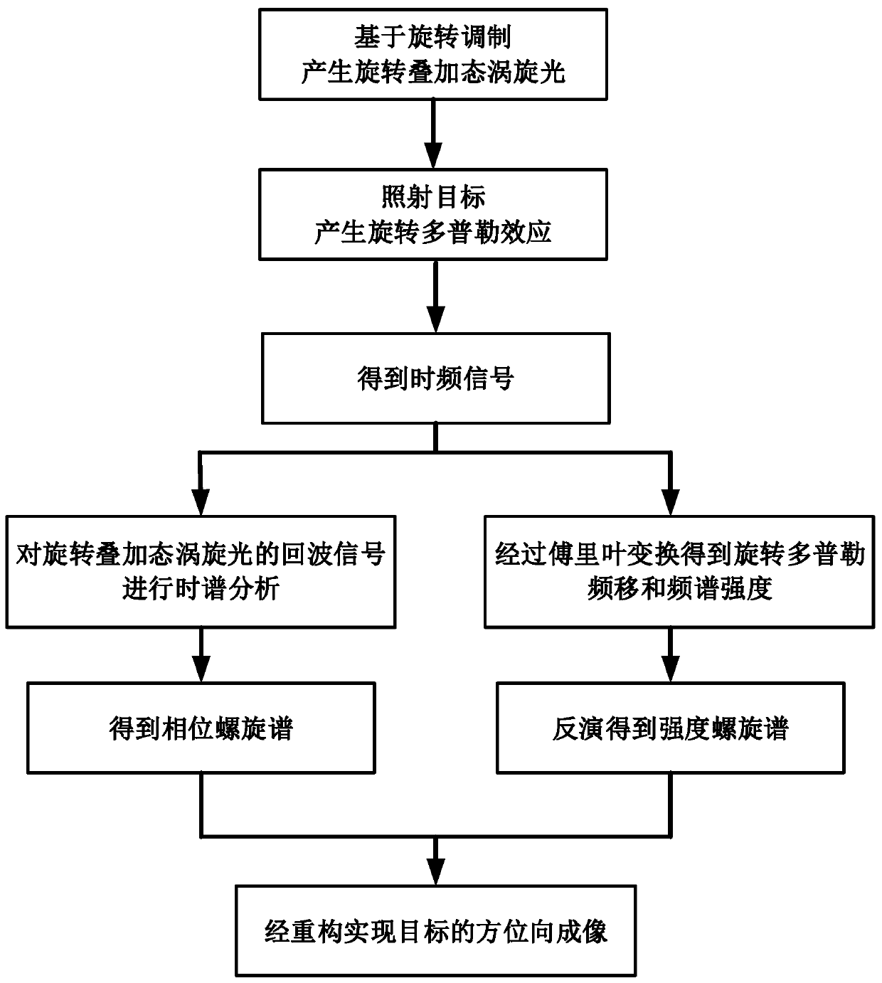
[0062] In the present invention, the vortex light in the rotating superposition state is used as the detection information carrier, and the target imaging flow chart is as follows figure 2 As shown, the specific implementation steps are as follows:

[0063] (1) Generation of rotating superposition vortex light with high-order angular momentum

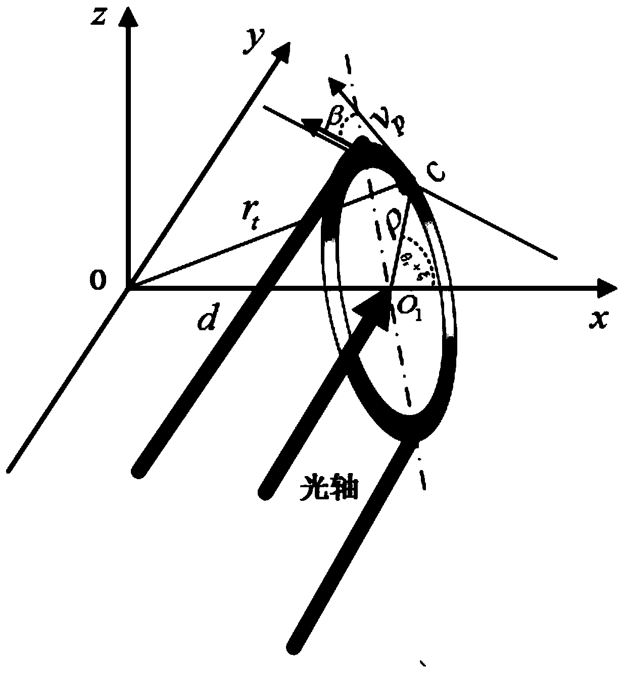
[0064] For a typical vortex Laguerre-Gaussian beam, the phase of the light field is uncertain at the center of the propagation direction, but the amplitude is 0, and the center point is also called a phase singularity. The light field expression is:

[0065]

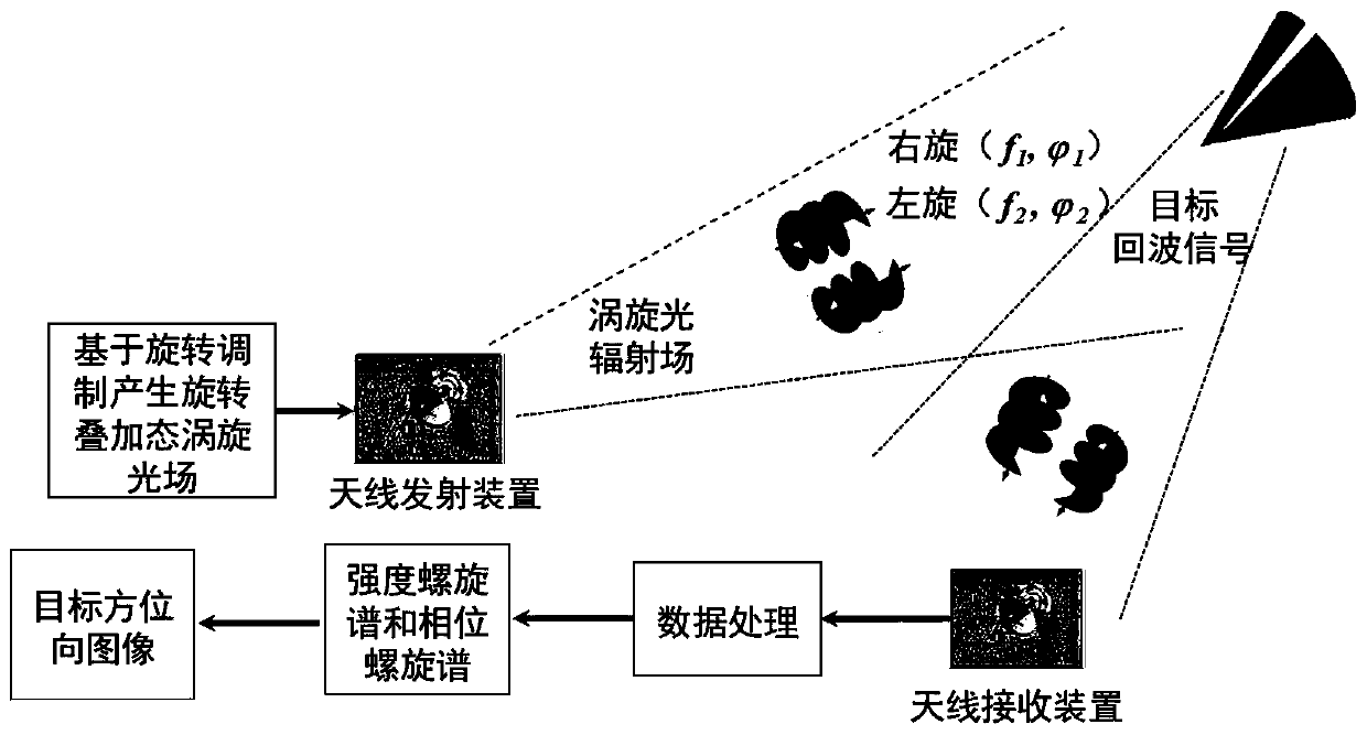
[0066] like image 3 As shown, the topological charge generated by the antenna transmitting device is l, and the frequency and phase are respectively f 1 , The left-handed vortex light at the same time produces a topological charge of -l, a frequency and a phase of f 2 , The right-handed vortex light, left-handed vortex light and right-handed vortex light are superimpos...


PUM


Abstract

The invention relates to a target azimuth imaging method based on superimposed vortex light. The method comprises the steps: generating a rotation superposition state vortex light irradiation target with different time-varying phase differences based on rotation modulation; generating rotation Doppler effect, performing fourier transform on the target echo signal to obtain a time-frequency signal;obtaining an intensity spiral spectrum of the rotation superposition state vortex light by utilizing a space-time inversion relationship between the rotation Doppler frequency shift signal and the intensity spiral spectrum, and carrying out time spectrum analysis on echo signals of the rotation superposition state vortex light with different time-varying phase differences to obtain a phase spiralspectrum of the rotation superposition state vortex light; and finally, realizing azimuth imaging of the target through reconstruction by superposition of the intensity spiral spectrum and the phasespiral spectrum of the vortex light in the rotation superposition state. The method has high imaging resolution under the foresight / staring imaging condition, and imaging is achieved without dependingon motion and benefited by motion.

Description

technical field [0001] The present invention mainly relates to the fields of optics, physics, photoelectric conversion, signal detection and optical imaging, especially technical methods such as phase and frequency modulation and demodulation. Background technique [0002] Synthetic Aperture Laser Radar (SAL) moves the traditional synthetic aperture technology from the microwave band to the laser band. Through the combination of synthetic aperture technology and laser characteristics, SAL can achieve better resolution by using the characteristics of short wavelength of laser, so SAL will play an important role in the field of ultra-high resolution imaging and recognition. [0003] Similar to the SAR system, when the SAL system is imaging, the radar platform moves along the azimuth direction at a speed V, and continuously sends signals to the surveying strip and receives the echoes of the target during the movement. If P1 and P2 are the positions of the radar platform at two...

Claims


Application Information

Patent Timeline
Patent Type & Authority Applications(China)
IPC IPC(8): G01S17/90
Inventor 任元陈琳琳刘通陈晓岑沙启蒙王琛王丽芬
Owner PLA PEOPLES LIBERATION ARMY OF CHINA STRATEGIC SUPPORT FORCE AEROSPACE ENG UNIV
Why Eureka
Try Eureka