Injection-molded wire harness and molding method

An injection molding and wire harness technology, applied in the field of wire harnesses, can solve problems such as combustion accidents, unprotected cables, short circuits, etc., and achieve the effects of reducing processing time, improving product quality, and improving service life.

Pending Publication Date: 2020-07-31
CHANGCHUN JETTY AUTOMOTIVE PARTS CORP
View PDF1 Cites 3 Cited by
  • Summary
  • Abstract
  • Description
  • Claims
  • Application Information

AI Technical Summary

Problems solved by technology

[0006] For this reason, the Chinese invention patent application CN 104149770A discloses an injection-molded anti-lock braking system sensor wire harness. On the original signal transmission cable, an injection-molded positioning part is added, but this invention is only for anti-lock braking system sensing. Wire harness, there are limitations in use
This invention still needs to purchase the finished cable, and then process it into the main body of the wire harness, which cannot save the cost of the wire harness
This invention does not protect the cable. After loading and using, the cable insulation will be damaged due to vibration and friction with the installation part. In severe cases, it will cause a short circuit and cause a combustion accident.
In addition, the injection molding parts added by this invention have a single function and cannot meet other complicated needs on the wiring harness.

Method used


Image

  • Injection-molded wire harness and molding method
  • Injection-molded wire harness and molding method
  • Injection-molded wire harness and molding method

Examples


Embodiment 1

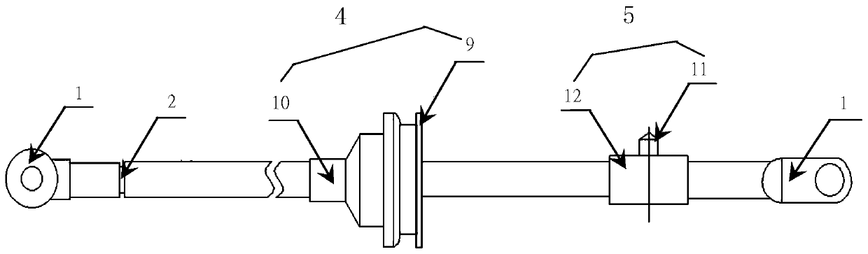
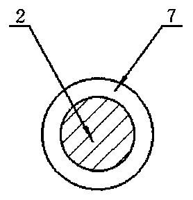
[0077] Such as figure 1 , Figure 3-1 As shown, the wiring harness is composed of a single conductor, and the two ends of the conductor 2 are respectively connected to the terminals 1 . The terminal 1 is a copper terminal, and the copper terminal is made of a copper alloy with a copper content of 60%, which can ensure good electrical conductivity and workability of the copper terminal. The surface of the terminal 1 is plated with nickel, and can also be plated with one of cadmium, zirconium, chromium, cobalt, manganese, aluminum, tin, titanium, zinc, copper, silver or gold. The coating can slow down the corrosion of the terminal and prolong the service life of the terminal . One end of the terminal 1 is connected to the conductor 2, and the other end of the terminal 1 is used to connect the electrical circuit of the electric device when in use. In this embodiment, the conductor 2 is composed of multi-core wires, and the cross-section of the multi-core wires is circular. In o...

Embodiment 2

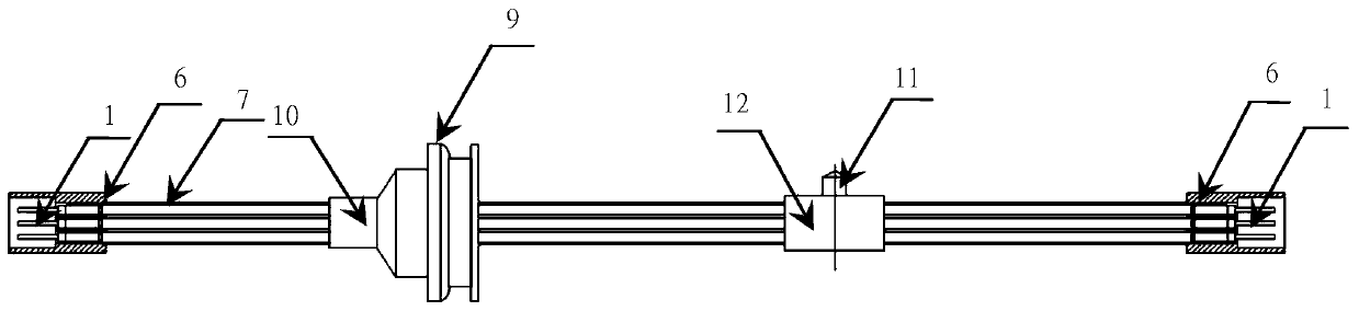
[0087] Such as figure 2 , Figure 3-2 , Figure 3-3 As shown, the wiring harness is composed of more than one conductor 2, and each of the conductors 2 is connected to the terminal 1 at both ends, and the surface of the terminal 1 is galvanized, and nickel, cadmium, zirconium, chromium, cobalt can also be plated , manganese, aluminum, tin, titanium, copper, silver or gold. The conductor 2 and the terminal 1 are the same as those in Embodiment 1, and will not be repeated here. The difference from Embodiment 1 is that the wire harness is also provided with at least one sheath 6 that is plugged into the electrical device. After the conductor 2 is connected to the terminal 1, the terminal 1 is assembled in the sheath 6. The terminals 1 are corresponding to different holes of the sheath 6 according to design requirements, so as to function together with different circuits, and at the same time, protect the terminals 1 from damage. The sheath 6 is integrally injection molded on...

Embodiment 3

[0097] Such as Figure 4 As shown, the wiring harness is composed of more than one conductor 2, one part of the conductor 2 is connected to the terminal 1, and the other part of the conductor 2 is connected to the conductor connection point according to the circuit requirements by crimping or welding. . The surface of the terminal 1 is plated with silver, and may also be plated with one of nickel, cadmium, zirconium, chromium, cobalt, manganese, aluminum, tin, titanium, zinc or gold. After the conductor 2 is connected to the terminal 1, the terminal 1 is assembled into a sheath 6 that is plugged in with the electrical device, and different terminals 1 correspond to different holes in the sheath 6 according to design requirements. During the preparation, the entire connection point of the conductor is sealed as a wire harness protection device 8; the wire harness protection device 8 is a rubber or plastic part processed by injection molding. Such as Figure 3-4 As shown, an ...


PUM


Abstract

The invention relates to an injection-molded wire harness and a molding method. The wire harness comprises a terminal and at least one conductor, wherein one end of the terminal is connected with an electrical loop of an electric device, the other end of the terminal is connected with the conductor, and the wire harness is provided with a protection layer which is formed by injection molding and wraps the conductor, and at least one positioning device which is formed by injection molding and is used for fixing the position of the wire harness or/and a sealing device for water prevention. According to the invention, manual operation can be reduced, the consistency of wire harness products is improved, the production cost of the wire harness products is reduced, and the service life of the wire harness is prolonged.

Description

technical field [0001] The invention relates to the technical field of wire harnesses, in particular to an injection-molded wire harness and a molding method. Background technique [0002] In the field of electrical connection, the wiring harness, as a bridge connecting the electrical circuit, connects the power supply and the electrical appliances, and the electrical appliances for data exchange. [0003] The way and material of the wire harness are very different, but the main structure is composed of cables, terminals, sheaths, fixing devices, waterproof devices, etc., wherein the cables are composed of conductors and insulating layers wrapped around the conductors. At present, the processing technology of wire harness is relatively complicated, including wire cutting, stripping, terminal crimping, welding, pipe penetration, blind plugging, terminal insertion, sheath insertion, subpackaging, wiring, rubber covering, branch fixing, installation positioning device, installa...

Claims


Application Information

Patent Timeline
Patent Type & Authority Applications(China)
IPC IPC(8): H01R4/02H01R4/18H01R13/02H01R13/502H01R13/52H01R31/06H01R43/02H01R43/048H01R43/24H01B7/00H01B7/17H01B7/40H01B13/22H01B13/32B60R16/02B29C45/14B29L31/34
CPCH01R13/502H01R13/02H01R4/18H01R4/023H01R13/52H01R31/06H01R43/02H01R43/048H01R43/24H01B13/22H01B13/32H01B7/0009H01B7/0045H01B7/17H01B7/40B60R16/0207B29C45/14H01R2201/26B29L2031/3462H01B13/012B29C45/14639B29C45/14598B60R16/0222B60Y2410/115H01B13/06H01R4/70H01R13/5205H01R43/005
Inventor 王超
Owner CHANGCHUN JETTY AUTOMOTIVE PARTS CORP
Why Eureka
Try Eureka