Eureka AIR delivers breakthrough ideas for toughest innovation challenges, trusted by R&D personnel around the world.

Chain pin shaft carbonitriding process

A technology of carbonitriding and pin shaft, which is applied in the direction of metal material coating process, coating, solid-state diffusion coating, etc., can solve the problem of affecting product durability, surface hardness and wear resistance cannot be further improved, and high hardness requirements problems, to achieve the effect of eliminating internal stress, breaking through technical bottlenecks, and high fatigue strength

Pending Publication Date: 2020-08-07
湖州求精汽车链传动有限公司
View PDF5 Cites 2 Cited by
  • Summary
  • Abstract
  • Description
  • Claims
  • Application Information

AI Technical Summary

Problems solved by technology

After the traditional carbonitriding process, the surface metallographic structure of the workpiece is: cryptocicular tempered martensite (grade 1-2) + carbonitride + retained austenite, and the retained austenite content is about 5-10%, the residual austenite affects the hardness and wear resistance of the part surface, so using this process as the final heat treatment workpiece, the surface hardness and wear resistance cannot be further improved, resulting in technical bottlenecks
The chain pin, as the connecting piece between the chain plates, requires high hardness, which directly affects the durability of the product. At present, the upper limit of the hardness of the chain pin produced by the traditional carbonitriding process is 750HV0.1, and the product is continuously improved. At present, this upper limit of hardness needs to be broken through urgently. Therefore, it is the current general trend to develop a new carbonitriding process for chain pin shafts.

Method used


Image

  • Chain pin shaft carbonitriding process
  • Chain pin shaft carbonitriding process
  • Chain pin shaft carbonitriding process

Examples


Embodiment 1

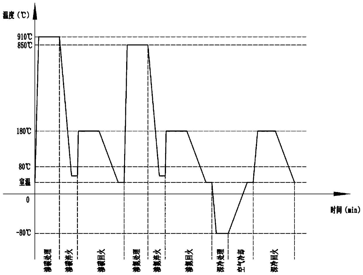
[0023] Embodiment 1: chain pin carbonitriding process, comprising the following steps:

[0024] Step A, carburizing treatment: carburizing the workpiece in a mesh belt furnace or a converter, the carburizing medium is methanol and kerosene, the heating temperature is 895-925°C, and the holding time is 35-45min;

[0025] Step B, carburizing and quenching: after the carburizing treatment holding time is reached, the workpiece is rapidly quenched with quenching oil at 20-80°C;

[0026] Step C, carburizing and tempering: heat the workpiece that has been carburized and quenched to 170-190°C and keep it warm for 170-190min to perform low-temperature tempering;

[0027] Step D, nitriding treatment: carry out nitriding treatment on the workpiece in a mesh belt furnace or a converter, the nitriding medium is ammonia gas, the heating temperature is 835-865°C, and the holding time is 40-60 minutes;

[0028] Step E, nitriding and quenching: after the nitriding treatment holding time is r...

Embodiment 2

[0038] Embodiment 2: chain pin carbonitriding process, comprising the following steps:

[0039] Step A, carburizing treatment: carburizing the workpiece in a mesh belt furnace, the carburizing medium is methanol and kerosene, wherein the input flow rate of the carburizing medium methanol is 2.0mL / min, and the input flow rate of the carburizing medium kerosene is 3.0 mL / min, heating temperature 895°C, holding time 35min;

[0040] Step B, carburizing and quenching: after the carburizing treatment holding time is reached, the workpiece is rapidly quenched with quenching oil at 20°C;

[0041] Step C, carburizing and tempering: heat the workpiece that has been carburized and quenched to 170°C and keep it warm for 170min to perform low-temperature tempering;

[0042] Step D, nitriding treatment: carry out nitriding treatment on the workpiece in a mesh belt furnace, the nitriding medium is ammonia gas, wherein the flow rate of ammonia gas into the nitriding medium is 350L / h, the hea...

Embodiment 3

[0048] Embodiment 3: chain pin shaft carbonitriding process, comprises the following steps:

[0049]Step A, carburizing treatment: carry out carburizing treatment to workpiece in converter, carburizing medium is methanol and kerosene, wherein the input flow rate of carburizing medium methanol is 2.5mL / min, the input flow rate of carburizing medium kerosene is 3.5mL / min min, heating temperature 925°C, holding time 45min;

[0050] Step B, carburizing and quenching: after the carburizing treatment holding time is reached, the workpiece is rapidly quenched with 80°C quenching oil;

[0051] Step C, carburizing and tempering: heat the workpiece that has been carburized and quenched to 190°C and keep it warm for 190min to perform low-temperature tempering;

[0052] Step D, nitriding treatment: carry out nitriding treatment on the workpiece in the converter, the nitriding medium is ammonia gas, wherein the flow rate of ammonia gas into the nitriding medium is 400L / h, the heating temp...


PUM

PropertyMeasurementUnit
Hardnessaaaaaaaaaa

Abstract

The invention discloses a chain pin shaft carbonitriding process. The chain pin shaft carbonitriding process comprises the following steps of A, carburizing treatment, wherein a carburizing medium ismethanol and kerosene; B, carburizing quenching, namely, quickly quenching a workpiece by using quenching oil at 20 to 80 DEG C; C, carburizing tempering, namely, heating the workpiece to 170 to 190 DEG C and keeping the temperature for 170 to 190 minutes to perform low-temperature tempering; D, nitriding treatment, wherein a nitriding medium is ammonia gas; E, nitriding quenching, namely, quicklyquenching the workpiece by using the quenching oil at 20 to 80 DEG C; F, nitriding tempering, namely, heating the workpiece to 170 to 190 DEG C and keeping the temperature for 170 to 190 minutes to perform low-temperature tempering; G, cryogenic treatment, wherein the cryogenic temperature is -90 to -70 DEG C, and temperature keeping time is 90 to 120 minutes; H, air cooling, namely, placing theworkpiece in air to restore room temperature; and I, cryogenic tempering, namely, heating the workpiece to 170 to 190 DEG C and keeping the temperature for 170 to 190 minutes to perform low-temperature tempering. The chain pin shaft carbonitriding process has the advantages of reducing the residual austenite content of the workpiece after heat treatment and improving the surface hardness and the wear resistance of the workpiece.

Description

technical field [0001] The invention relates to a carbonitriding process, in particular to a carbonitriding process for a chain pin shaft. Background technique [0002] At present, the traditional carbonitriding process uses methanol, ammonia, propane and other co-infiltration media to provide an atmosphere for heat treatment of the workpiece at the same time. Enhance technical requirements such as workpiece strength and wear resistance. After the traditional carbonitriding process, the surface metallographic structure of the workpiece is: cryptocicular tempered martensite (grade 1-2) + carbonitride + retained austenite, and the retained austenite content is about 5-10%, the residual austenite affects the hardness and wear resistance of the part surface, so using this process as the final heat treatment of the workpiece, the surface hardness and wear resistance cannot be further improved, resulting in a technical bottleneck. The chain pin, as the connecting piece between t...

Claims


Application Information

Patent Timeline
IPC IPC(8): C23C8/30
CPCC23C8/30
Inventor 赵旭东钱江徐秀琴吴建明翁建良尹德兵沈晓怡
Owner 湖州求精汽车链传动有限公司
Why Eureka
Eureka Blog
Learn More