Pneumatic valve used for industrial gas environment-friendly treatment equipment
An environmental protection treatment, industrial gas technology, applied in the direction of sliding valves, mechanical equipment, liquid separation agent, etc., can solve the problems of accumulation, valve damage, gas does not have filtering effect, etc., achieve high washing efficiency, keep clean, improve The effect of sewage discharge efficiency
- Summary
- Abstract
- Description
- Claims
- Application Information
AI Technical Summary
Problems solved by technology
Method used
Image
Examples
Embodiment 1
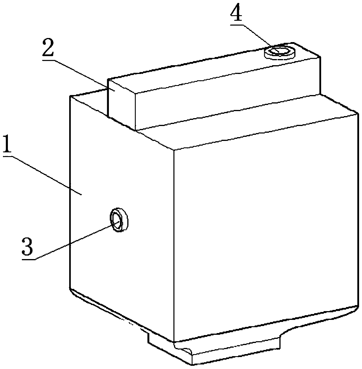
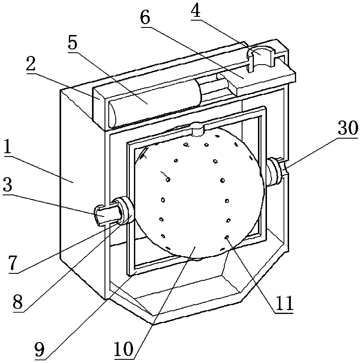
[0044] Such as Figure 1-3 As shown, a pneumatic valve for industrial gas environmental protection treatment equipment includes a valve body 1, a cylinder 5 is fixedly connected to the top of the valve body 1, the piston rod of the cylinder 5 is fixedly connected to the valve core 6, and the valve core 6 is connected to the valve body 1 The exhaust port 4 of the valve body 1 is slidably connected, and the inside of the valve body 1 is connected with a washing ball 10. The bottom end of the washing ball 10 communicates with the air inlet 3 on the left side of the valve body 1 through the frame 9, and the top end of the washing ball 10 communicates with the valve body through the frame 9. The water injection port 30 on the left side of 1 is connected, the side of the washing ball 10 is provided with a number of through holes 11, the inside of the washing ball 10 is provided with a rolling ball 12, and the bottom end of the valve body 1 is connected with a drainage mechanism.
[...
Embodiment 2
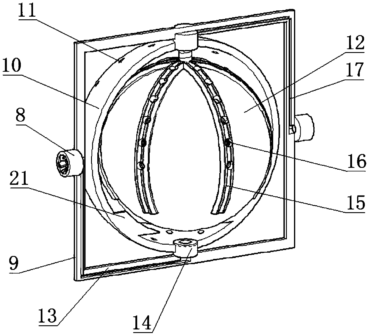
[0047] Such as Figure 1-4 As shown, a pneumatic valve for industrial gas environmental protection treatment equipment includes a valve body 1, a cylinder 5 is fixedly connected to the top of the valve body 1, the piston rod of the cylinder 5 is fixedly connected to the valve core 6, and the valve core 6 is connected to the valve body 1 The exhaust port 4 of the valve body 1 is slidably connected, and the inside of the valve body 1 is connected with a washing ball 10. The bottom end of the washing ball 10 communicates with the air inlet 3 on the left side of the valve body 1 through the frame 9, and the top end of the washing ball 10 communicates with the valve body through the frame 9. 1 The water injection port 30 on the left side is connected, the side of the washing ball 10 is provided with a number of through holes 11, the inside of the washing ball 10 is provided with a rolling ball 12, the bottom of the valve body 1 is connected with a drainage mechanism, and the frame 9...
Embodiment 3
[0050] Such as Figure 1-5 As shown, a pneumatic valve for industrial gas environmental protection treatment equipment includes a valve body 1, a cylinder 5 is fixedly connected to the top of the valve body 1, the piston rod of the cylinder 5 is fixedly connected to the valve core 6, and the valve core 6 is connected to the valve body 1 The exhaust port 4 of the valve body 1 is slidably connected, and the inside of the valve body 1 is connected with a washing ball 10. The bottom end of the washing ball 10 communicates with the air inlet 3 on the left side of the valve body 1 through the frame 9, and the top end of the washing ball 10 communicates with the valve body through the frame 9. 1. The water injection port 30 on the left side is connected. The side of the washing ball 10 is provided with several through holes 11. The inside of the washing ball 10 is provided with a rolling ball 12. The bottom end of the valve body 1 is connected with a drainage mechanism. The shape of t...
PUM
 Abstract
Description
Claims
Application Information
 - R&D
- Intellectual Property
- Life Sciences
- Materials
- Tech Scout
- Unparalleled Data Quality
- Higher Quality Content
- 60% Fewer Hallucinations
Browse by: Latest US Patents, China's latest patents, Technical Efficacy Thesaurus, Application Domain, Technology Topic, Popular Technical Reports.
© 2025 PatSnap. All rights reserved.Legal|Privacy policy|Modern Slavery Act Transparency Statement|Sitemap|About US| Contact US: help@patsnap.com


