Rotational atherectomy interventional treatment instrument for treating coronary artery calcification lesion
A technology for interventional therapy and coronary artery, applied in the direction of surgical cutting instruments, etc., can solve the problems of rotational atherectomy guide wire deformation, coronary artery damage, large errors, etc., to achieve the effect of simple operation, saving operation time, and reducing medical accidents.
- Summary
- Abstract
- Description
- Claims
- Application Information
AI Technical Summary
Problems solved by technology
Method used
Image
Examples
Embodiment 1
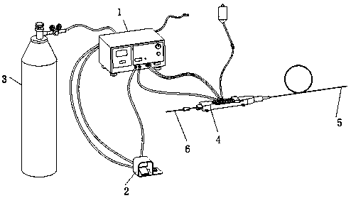
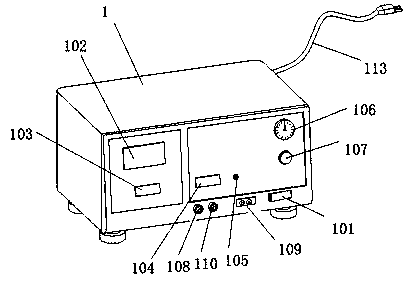
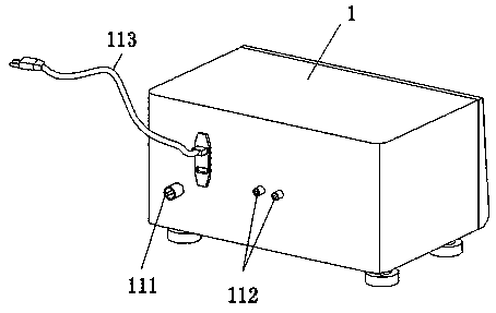
[0058] A rotary atherectomy interventional therapy instrument for treating calcified coronary lesions, such as figure 1 As shown, it includes a rotational atherectomy instrument host 1, a pedal control panel 2, a nitrogen tank 3, a propeller 4, a rotational atherectomy catheter 5 and a rotational atherectomy guide wire 6; as figure 2 and image 3 As shown, the front of the main body of the rotary atherometer 1 is provided with a power switch key 101, a rotational speed display 102, a single rotation atherectomy time display 103, an accumulated time display 104, a reset button 105, a turbine pressure gauge 106, and a turbine adjustment knob 107 , a deceleration valve connector 108, a propeller fiber optic connector 109 and a propeller gas connection pipe joint 110, the back of the rotary atherometer host 1 is provided with a nitrogen interface 111, a foot switch hose interface 112 and a power cord 113;
[0059] Such as Figure 5 As shown, the pedal control panel 2 is provide...
Embodiment 2
[0066] On the basis of Example 1, as Figure 10 As shown, the outer walls of the two vertical plates 4082 are provided with screw holes 4084, and the insides of the screw holes 4084 are threaded with screw rods 4085. One end of the screw rod 4085 is fixed with a first rubber pad 4086, and the other end is fixed with a quincunx knob 4087.
[0067] In this embodiment, when the stroke control structure 408 is used, rotating the plum blossom-shaped knob 4087 will drive the screw rod 4085 and the first rubber pad 4086 to rotate forward or backward, and the first rubber pad 408 can be made to fix the position.
Embodiment 3
[0069] On the basis of Example 1, as Figure 11 and Figure 12 As shown, the outer walls of the two vertical plates 4082 are provided with square holes 4084A, and the upper edge of the square holes 4084A is fixed on the hinged seat 4085A, and the splint 4087A is fixed on the hinged seat 4085A through the hinge shaft 4086A, and the outer wall cover of the hinge shaft 4086A A torsion spring 4088A is provided, and a second rubber pad 4089A is fixed on the inner side wall of the splint 4087A.
[0070] In this embodiment, when the stroke control structure 408 needs to be moved, the splint 4087A can be pressed, and then the crossbar 4081 can be moved. When it needs to be fixed, the splint 4087A is released, and the splint 4087A will rotate downward under the action of the torsion spring 4088A. Until the second rubber pad 4089A touches the outer surface of the fuselage 401 , under the frictional force of the second rubber pad 4089A, the movement stroke control structure 408 will not m...
PUM
| Property | Measurement | Unit |
|---|---|---|
| Length | aaaaa | aaaaa |
| Length | aaaaa | aaaaa |
Abstract
Description
Claims
Application Information
 - R&D
- Intellectual Property
- Life Sciences
- Materials
- Tech Scout
- Unparalleled Data Quality
- Higher Quality Content
- 60% Fewer Hallucinations
Browse by: Latest US Patents, China's latest patents, Technical Efficacy Thesaurus, Application Domain, Technology Topic, Popular Technical Reports.
© 2025 PatSnap. All rights reserved.Legal|Privacy policy|Modern Slavery Act Transparency Statement|Sitemap|About US| Contact US: help@patsnap.com


