
On-line monitoring device for simulated wire icing based on the law of icing in micro-topographic and micro-meteorological regions

A monitoring device and micro-meteorological technology, which is applied in the direction of measuring devices, cable installation, overhead installation, etc., can solve the problems of failure to achieve the expected effect, excessive temperature drift, and unsatisfactory, so as to enhance the actual application ability and avoid error amplification , Realize the effect of online monitoring

Active Publication Date: 2021-12-24
CHONGQING GRID CONSTR +3
View PDF6 Cites 0 Cited by
  • Summary
  • Abstract
  • Description
  • Claims
  • Application Information

AI Technical Summary

Problems solved by technology

At present, the means of line icing monitoring mainly include: line icing on-line monitoring method based on inclination and stress, icing monitoring method based on stress and conductor sag, image method and meteorological parameter prediction method, the first two methods are installed on the line However, since the sensor is directly installed on the line, the sensor will be affected by electromagnetic interference at a high voltage level, resulting in a large error. At the same time, in winter, the sensor is affected by low temperature. , it will make its temperature drift too large, even exceed the working temperature range, or freeze, making it unusable. In addition, the monitoring needs to be converted and calculated by multi-sensor measurement data, which will further amplify the error of the sensor itself. Therefore, this type of monitoring None of the methods can achieve the expected effect in practical application, and the use value is low; for the image method and the prediction method, the former uses image processing to compare and analyze the graphics before and after the line is covered with ice, and obtains the data of the thickness of the ice, but due to the image The processing technology is immature, and there are problems in the acquisition of actual images, so it has not been applied. The prediction method is only based on the historical icing data, and the icing meteorological parameter prediction model is constructed, which itself belongs to an indirect acquisition line. The error of the ice thickness method is more obvious than other methods, so it is only used for reference in practice and cannot be used as a monitoring method
[0003] To sum up, the existing on-line icing monitoring methods of power grid lines have certain problems and cannot meet the needs of line icing monitoring in actual operation. Therefore, it is necessary to propose a new online icing monitoring method

Method used


Image

  • On-line monitoring device for simulated wire icing based on the law of icing in micro-topographic and micro-meteorological regions
  • On-line monitoring device for simulated wire icing based on the law of icing in micro-topographic and micro-meteorological regions
  • On-line monitoring device for simulated wire icing based on the law of icing in micro-topographic and micro-meteorological regions

Examples


Embodiment 1

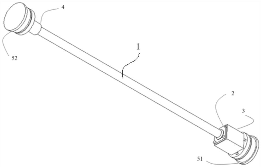
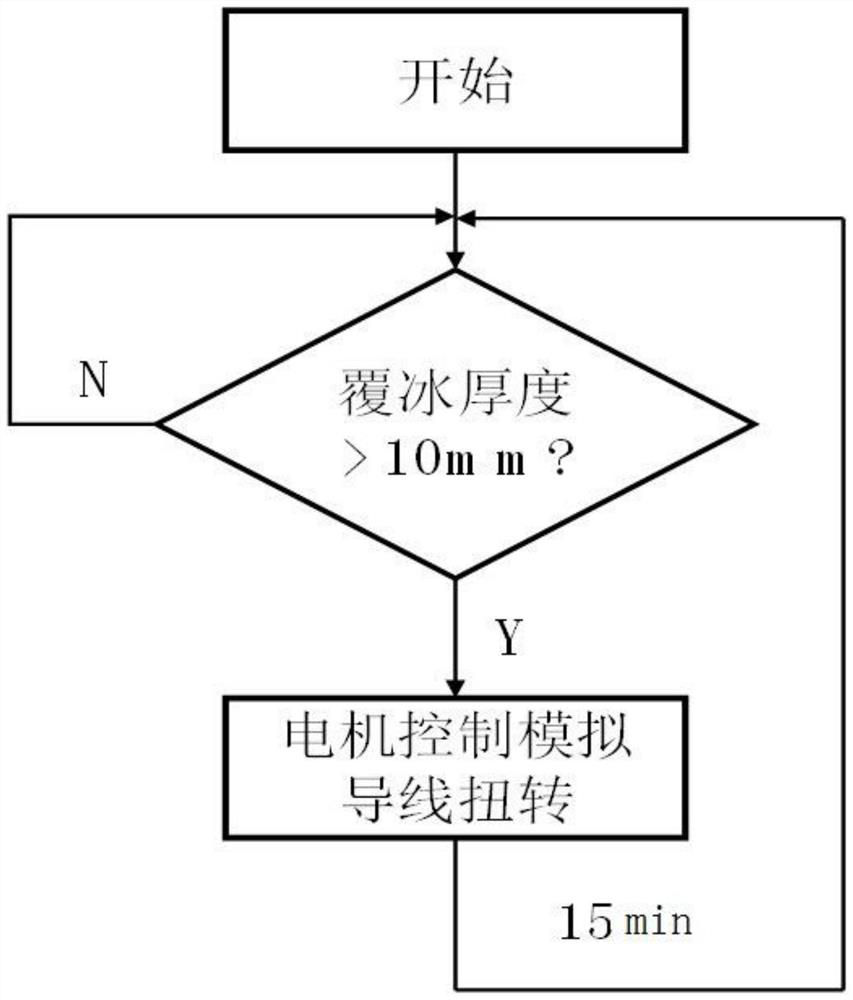
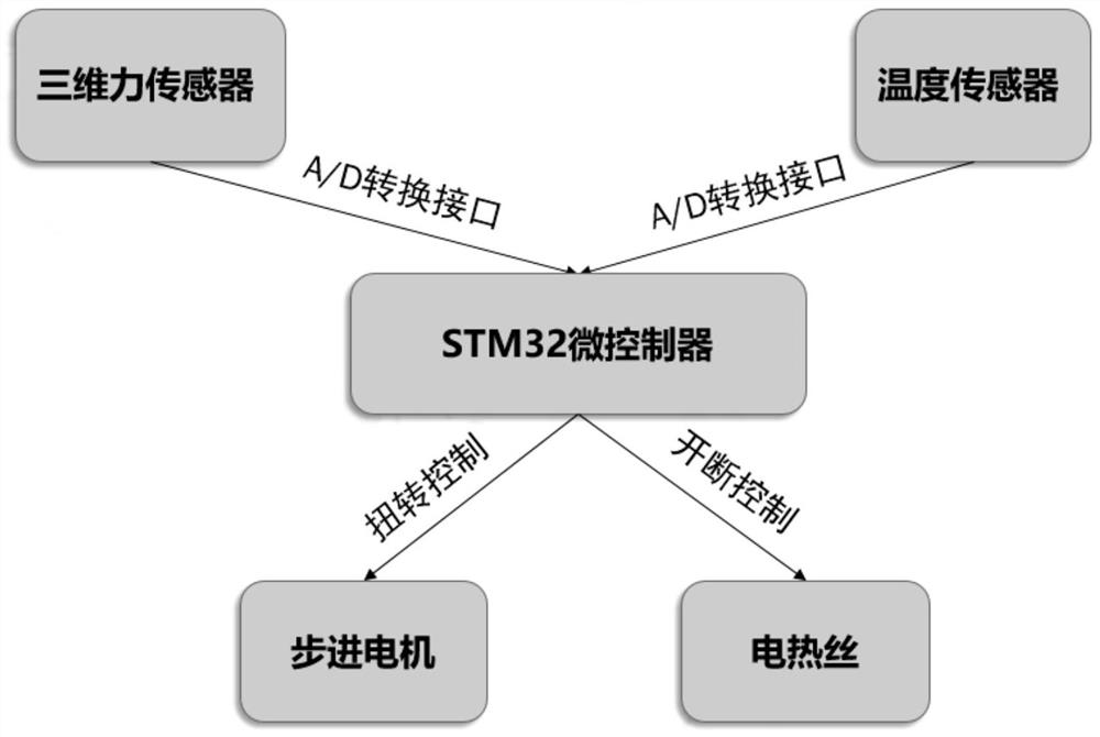
[0057] see Figure 1 to Figure 3 , an on-line monitoring device for icing on simulated wires based on the icing law in micro-topographic and micro-meteorological regions, mainly including simulated wires 1, stepping motor 2, motor fixing sleeve 3, rolling belt shaft bearing 4, sealing box I, sealing box II, Three-dimensional force sensor I51, stepper motor driver, three-dimensional force sensor II52, bracket, power supply, microcontroller I, microcontroller II, temperature sensor I, temperature sensor II, heating module I and heating module II.

[0058] One end of the analog wire 1 is connected to the transmission shaft 1 of the stepping motor 2, and the other end is connected to the head end of the rolling belt shaft bearing 4.

[0059] The simulated wire 1 is parallel to the monitored transmission line. The type and material of the simulated wire 1 are the same as those of the power transmission wire.

[0060] Analog wire 1 is a steel-cored aluminum stranded wire with the ...

Embodiment 2

[0103] The online monitoring device for icing on simulated conductors based on the law of icing in micro-topography and micro-meteorological areas mainly includes simulated conductors 1, stepper motor 2, motor fixed bushing 3, rolling belt shaft bearing 4, sealed box I, sealed box II, three-dimensional Force sensor I51, three-dimensional force sensor II52, stepper motor driver, bracket, power supply, microcontroller I, microcontroller II, temperature sensor I, temperature sensor II, heating module I and heating module II.

[0104] One end of the analog wire 1 is connected to the transmission shaft 1 of the stepping motor 2, and the other end is connected to the head end of the rolling belt shaft bearing 4.

[0105] The end of the transmission shaft II of the stepping motor 2 is covered with a motor fixing sleeve 3 .

[0106] Said motor fixing sleeve 3 outer cover is provided with sealing box 1.

[0107] A three-dimensional force sensor 151, a stepping motor driver and a micro...

Embodiment 3

[0119] Based on the simulated wire icing on-line monitoring device for icing laws in micro-topographic and micro-meteorological regions, the main structure is shown in Embodiment 2, wherein the monitoring device also includes a microcontroller II, a temperature sensor I, a temperature sensor II, a heating module I and a heating module II.

[0120] The temperature sensor 1 and the heating module 1 are packaged in the sealed box 1.

[0121] Described temperature sensor 1 monitors the temperature t of sealed box 1 1 , and sent to the microcontroller I.

[0122] Described heating module 1 is connected with the I / O interface signal line of microcontroller 1.

[0123] When the microcontroller I receives the temperature t 1 min At this time, the microcontroller 1 communicates with the heating module 1 to provide a pulse signal for the heating module 1 to control the heating of the heating module 1.

[0124] When the microcontroller I receives the temperature t 1 >T max , microc...


PUM


Abstract

The invention discloses an on-line monitoring device for icing of simulated wires based on the law of icing in micro-topography and micro-meteorological areas, which mainly includes simulated wires, stepping motors, motor fixing sleeves, rolling belt shaft bearings, sealing boxes I, sealing boxes II, three-dimensional Force sensor I, 3D force sensor II, stepper motor driver, stand and microcontroller I. The invention can monitor the ice thickness of the power transmission line under the same meteorological environment, and the device has small volume and low power, and can be conveniently installed on the pole tower.

Description

technical field [0001] The invention relates to on-line monitoring of icing on transmission lines, in particular to an on-line icing monitoring device for simulated wires based on the law of icing in micro-topography and micro-meteorological regions. Background technique [0002] Transmission line is the main part of power transmission in the power grid. The normal operation of the line is an important guarantee for the safety of the power grid. The icing accident of the line has always been a major problem in the safe operation of the power grid, and it is a serious natural disaster in the power system. Therefore, the monitoring of the line ice thickness has become the key to solve the line ice problem. The more comprehensive the monitoring content and the stronger the timeliness of monitoring, the better it can guide the relevant departments to take anti-icing and de-icing in advance. Measures to avoid line icing accidents. At present, the means of line icing monitoring m...

Claims


Application Information

Patent Timeline
Patent Type & Authority Patents(China)
IPC IPC(8): G01D21/02G08B21/18G08C17/02H02G1/02H02G7/00
CPCG01D21/02H02G7/00H02G1/02G08B21/18G08C17/02
Inventor 李道武李贤初吴尧胡建林游亮蒋兴良曾林刘杰龚信举于龙陈启洪陈泽帆
Owner CHONGQING GRID CONSTR
Learn More