
Autonomous cooling polishing and grinding robot

A polishing and grinding, robot technology, applied in the field of workpiece processing, can solve the problems of no drying device, unfavorable automatic production, unable to form a process, etc., to achieve the effect of improving polishing and grinding efficiency and facilitating automatic processing

Inactive Publication Date: 2020-08-14
CHONGQING ACAD OF METROLOGY & QUALITY INST
View PDF11 Cites 1 Cited by
  • Summary
  • Abstract
  • Description
  • Claims
  • Application Information

AI Technical Summary

Problems solved by technology

[0004] 1. When the existing polishing and grinding robot processes the workpiece, because it only completes the polishing and grinding of the workpiece, a process cannot be formed, which is not conducive to automatic production and reduces the grinding efficiency;
[0005] 2. When the grinding disc of the existing polishing and grinding robot polishes the workpiece, the grinding disc will generate a large amount of heat, which needs to be cooled by cooling liquid. Generally, the polishing and grinding robot does not recycle the cooling liquid, which is easy to cause the cooling liquid waste;
[0006] 3. The existing polishing and grinding robot, in the process of transportation after polishing and grinding, does not have a drying device, which increases the labor load of later cleaning staff

Method used


Image

  • Autonomous cooling polishing and grinding robot
  • Autonomous cooling polishing and grinding robot
  • Autonomous cooling polishing and grinding robot

Examples


Embodiment 1

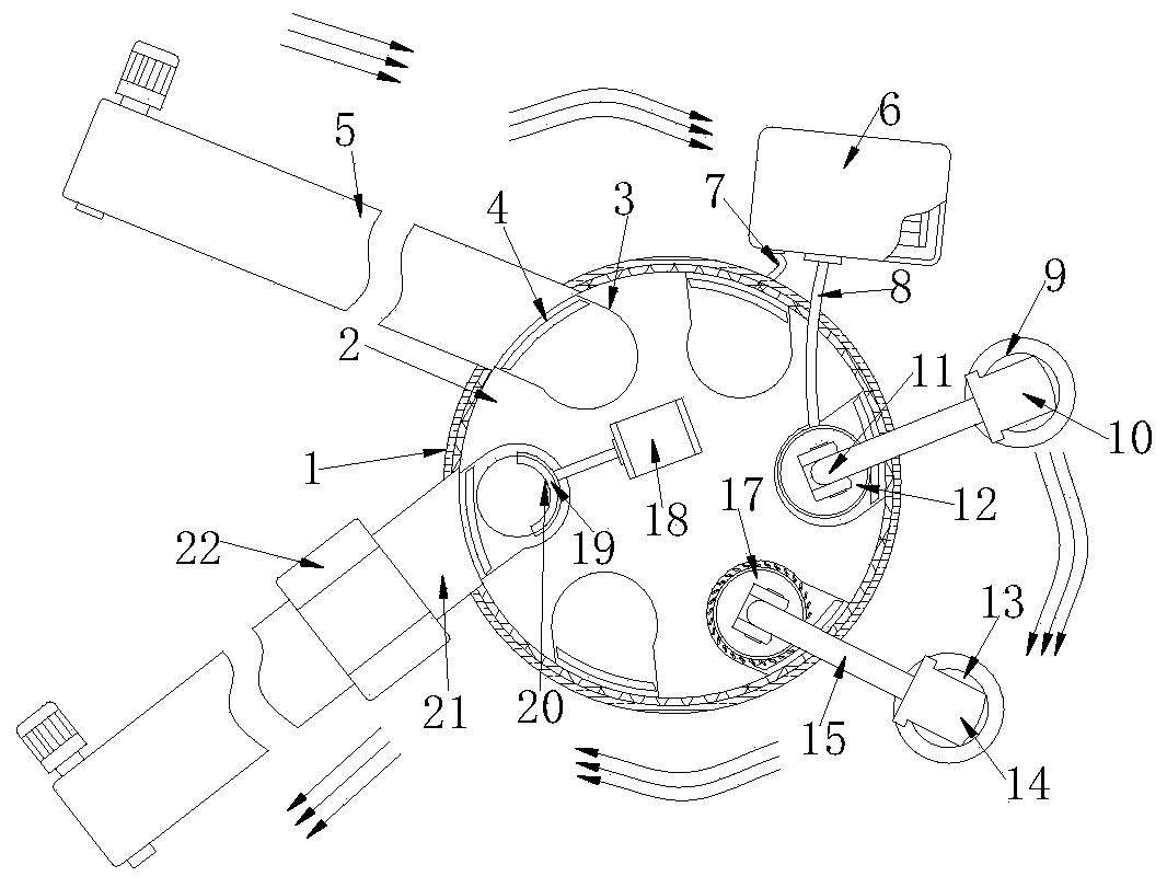
[0034] Such as figure 1 , Figure 4 and Figure 6 shown;

[0035] figure 1 It is a structural schematic diagram of the present invention;

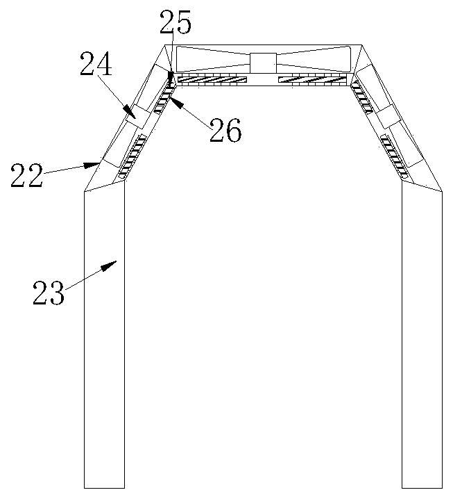
[0036] Figure 4 It is a connection side view of the fixed barrel and the rotating disk in the present invention;

[0037] Figure 6 is a flow chart in the present invention;

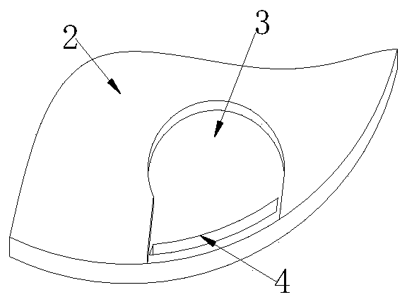
[0038]An autonomous cooling and polishing robot, comprising a turntable 2, a first base 9 is installed on one side of the turntable 2, a first telescopic rod 10 is installed on the upper surface of the first base 9, and the outer wall of the first telescopic rod 10 is fixedly connected with a second A rotary plate 11, the bottom surface of the first rotary plate 11 is rotatably connected with a grinding piece 12, the bottom surface of the rotary plate 2 is equipped with a fixed barrel 1, and the upper surface of the rotary plate 2 is provided with a plurality of concave placement grooves 3, the outer side of the rotary plate 2 The wall is connected with the ...


PUM


Abstract

The invention belongs to the technical field of workpiece machining, and particularly relates to an autonomous cooling polishing and grinding robot. The autonomous cooling polishing and grinding robotcomprises a rotary disc, a first base is installed on one side of the rotary disc, a first telescopic rod is installed on the upper surface of the first base, a first rotary plate is fixedly connected to the outer side wall of the first telescopic rod, a grinding part is rotationally connected to the bottom face of the end face of the first rotary plate, and a fixed barrel is installed on the bottom face of the rotary disc. A cleaning part which rotates rapidly sweeps away chippings on a workpiece, the cleaning effect is achieved, and finally, when the cleaning part rotates to a second conveying belt, a sensor detects the existence of the workpiece, an electric push rod descends to drive an air cylinder to descend, a telescopic shaft of the air cylinder drives a push plate to stretch out,the workpiece in a containing groove is pushed to the second conveying belt, and the second conveying belt completes the conveying process of the ground workpiece. In conclusion, automatic process operation is formed for polishing and grinding of the workpiece, automatic machining is facilitated, and the polishing and grinding efficiency is improved.

Description

technical field [0001] The invention belongs to the technical field of workpiece processing, and in particular relates to an autonomous cooling and polishing robot. Background technique [0002] A robot is an intelligent machine that can work semi-autonomously or fully autonomously. It has basic characteristics such as perception, decision-making, and execution. It can assist or even replace humans in completing dangerous, heavy, and complicated tasks, improve work efficiency and quality, serve human life, and expand Or extend the scope of human activities and capabilities. Machining refers to the process of changing the shape or performance of a workpiece through a mechanical device. According to the difference in processing methods, it can be divided into cutting processing and pressure processing. When processing a workpiece , also needs to go through the polishing and grinding step to ensure the surface smoothness and post-production quality of the workpiece. [0003] T...

Claims


Application Information

Patent Timeline
IPC IPC(8): B25J11/00B24B41/00B24B55/06B24B55/03F26B21/00
CPCB24B41/005B24B55/03B24B55/06B25J11/0065F26B21/001F26B21/004
Inventor 鹿安袁静于灵王锐
Owner CHONGQING ACAD OF METROLOGY & QUALITY INST
Learn More