Sludge drying and dewatering equipment and method

A technology of sludge drying and dewatering equipment, applied in the field of solid waste resource utilization, can solve the problems of easy hardening in the drying cavity, low dewatering efficiency, and difficulty in dewatering, and achieves the improvement of drying efficiency, reduction of dewatering costs, and reduction of equipment investment. Effect

Pending Publication Date: 2020-08-14
余佳萱
View PDF8 Cites 2 Cited by
  • Summary
  • Abstract
  • Description
  • Claims
  • Application Information

AI Technical Summary

Problems solved by technology

[0007] The purpose of the present invention is to overcome the problems of difficult dehydration, high energy consumption, low dehydration efficiency and easy hardening in the drying chamber when wet sludge is dried and dehydrated by existing equipment and methods, and to provide a method that can improve Dehydration efficiency and energy utilization efficiency, and drying and dehydration equipment and methods that can effectively avoid problems such as uneven heating, easy hardening and wall sticking of sludge indirect drying

Method used


Image

  • Sludge drying and dewatering equipment and method
  • Sludge drying and dewatering equipment and method

Examples


Embodiment 1

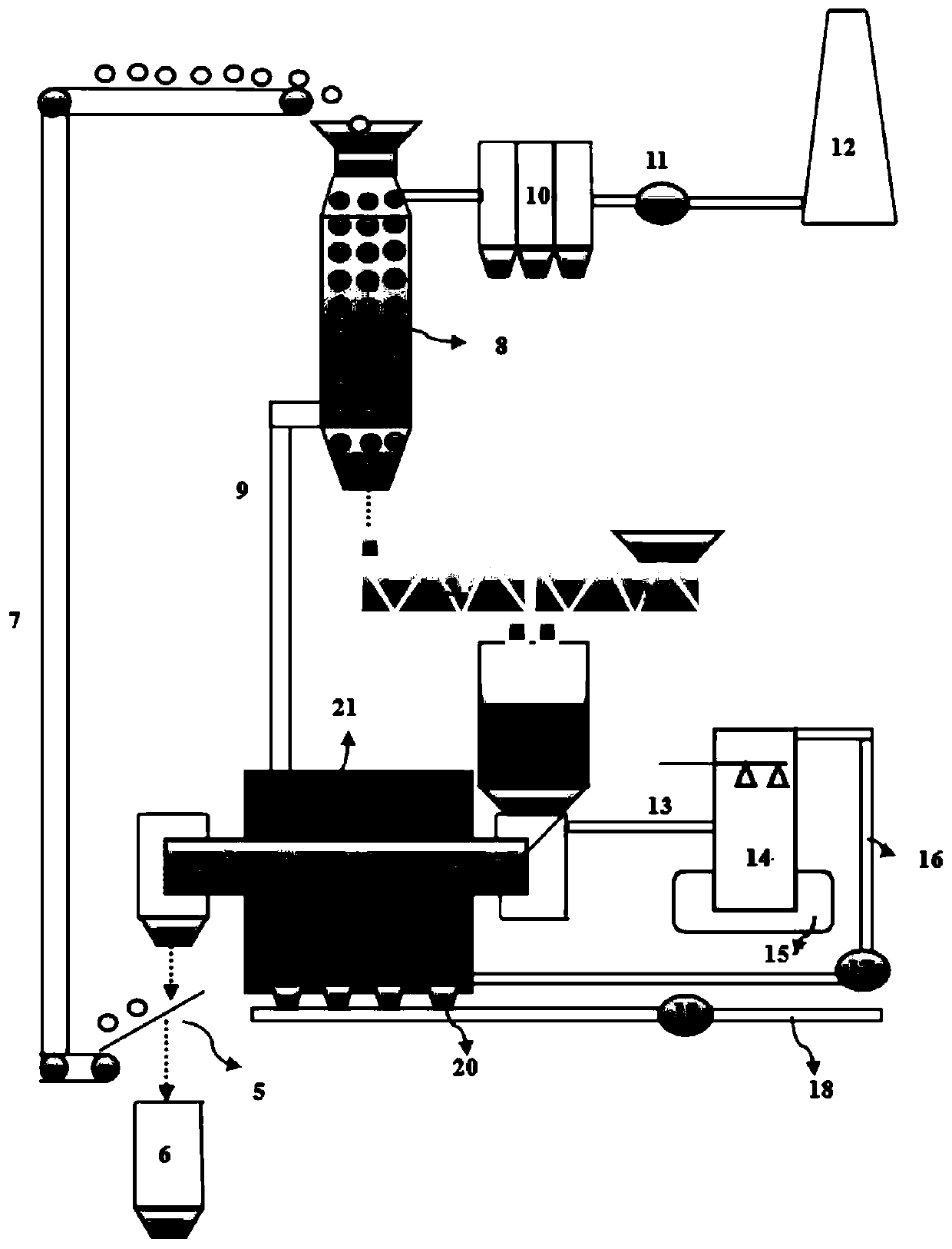
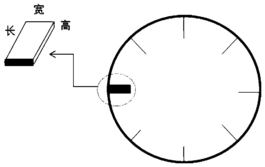
[0068] Such as figure 1 Shown, wet sludge and heat storage ball (the addition amount of heat storage ball is 10% of wet sludge volume; The moisture content of wet sludge is 85%; Heat storage ball is the spherical shape with smooth surface, and diameter is 0.5cm and The density is 5t / m 3 ) into the buffer bin 2 via 1# conveying device 1 and 2# conveying device 3 respectively, and then jointly enter the rotary drum indirect drying device 4 with a heating furnace temperature of 300°C (wet sludge and heat storage balls are indirectly dried on the rotary drum The filling rate in the device is 20%) to carry out internal and external synergistic drying and dehydration, and the dried material is screened by the screening device 5, and the undersize is dried sludge, which is directly sent to the dry sludge storage device 6, and the oversize It is a heat storage ball, which is transported to the waste heat recovery device 8 through the 3# conveying device 7, and is heated by the waste ...

Embodiment 2

[0070] Such as figure 1 As shown, the wet sludge and heat storage balls (the addition of heat storage balls is 20% of the wet sludge volume; the moisture content of wet sludge is 60%; the heat storage balls are spherical with a smooth surface, a diameter of 2cm and a density of 7.8t / m 3 ) into the buffer bin 2 via 1# conveying device 1 and 2# conveying device 3 respectively, and then jointly enter the rotary drum indirect drying device 4 with a heating furnace temperature of 400°C (wet sludge and heat storage balls are indirectly dried on the rotary drum The filling rate in the device is 20%) to carry out internal and external synergistic drying and dehydration, and the dried material is screened by the screening device 5, and the undersize is dried sludge, which is directly sent to the dry sludge storage device 6, and the oversize It is a heat storage ball, which is transported to the waste heat recovery device 8 through the 3# conveying device 7, and is heated by the waste ...

Embodiment 3

[0072] Such as figure 1 As shown, wet sludge and heat storage balls (the addition of heat storage balls is 30% of the volume of wet sludge; the moisture content of wet sludge is 40%; heat storage balls are spherical with smooth surface, diameter is 1cm and density 3t / m 3 ) into the buffer bin 2 via 1# conveying device 1 and 2# conveying device 3 respectively, and then jointly enter the rotary drum indirect drying device 4 with a heating furnace temperature of 200°C (wet sludge and heat storage balls are indirectly dried on the rotary drum The filling rate in the device is 10%) to carry out internal and external synergistic drying and dehydration, and the dried material is screened by the screening device 5, and the undersize is dried sludge, which is directly sent to the dry sludge storage device 6, and the oversize It is a heat storage ball, which is transported to the waste heat recovery device 8 through the 3# conveying device 7, and is heated by the waste heat of the flue...


PUM

PropertyMeasurementUnit
lengthaaaaaaaaaa
diameteraaaaaaaaaa
densityaaaaaaaaaa

Abstract

The invention belongs to the field of solid waste resource utilization, and relates to sludge drying and dewatering equipment and a sludge drying and dewatering method. The equipment comprises a 1 # conveying device (1), a surge bin (2), a 2 # conveying device (3), a rotary drum indirect drying device (4), a screening device (5), a dry sludge storage device (6), a 3 # conveying device (7) and a waste heat recovery device (8), wherein the 1 # conveying device (1) and the 2 # conveying device (3) are communicated with the surge bin (2); the surge bin (2), the rotary drum indirect drying device (4) and the screening device (5) are sequentially communicated; oversize products of the screening device (5) are conveyed into a waste heat recovery device (8) through the 3 # conveying device (7); materials in the waste heat recovery device (8) are conveyed back to the surge bin (2) through the 2 # conveying device (3). The equipment and the method provided by the invention have the advantages ofhigh dehydration efficiency and low energy consumption, and can effectively avoid the problems of easy hardening and easy wall adhesion in direct drying of sludge.

Description

technical field [0001] The invention belongs to the field of utilization of solid waste resources, and in particular relates to a sludge drying and dehydrating device and method. Background technique [0002] In recent years, with the advancement of industrialization and the continuous growth of population, the number of sewage treatment plants has continued to increase. It is estimated that my country's sludge production will exceed 70 million tons in 2020, with an average annual growth rate of over 11%. Wet sludge contains free water, interstitial water, surface water and chemically bound water. After the free and interstitial water is removed by the ordinary dehydration process, its moisture content is still as high as 70-85%. These waters are attached to the surface of the particles through hydrogen bonds, causing Sludge is difficult to deal with and the resource cost is high. Domestic sludge recycling technologies include landfill, composting, incineration, and pyrolys...

Claims


Application Information

Patent Timeline
Patent Type & Authority Applications(China)
IPC IPC(8): C02F11/13
CPCC02F11/13
Inventor 余佳萱余广炜卢敏
Owner 余佳萱
Why Eureka
Try Eureka