

Time domain A/D converter group
A converter and time-domain technology, applied in analog-to-digital converters, analog-to-digital conversion, code conversion, etc., can solve the problem of increased area, increased power consumption, and A/D converters that cannot be high-speed and low-power. Achieving high dynamic range of sensors, etc.
- Summary
- Abstract
- Description
- Claims
- Application Information
AI Technical Summary
Problems solved by technology
Method used
Image

Examples
no. 1 approach
[0138] (A / D converter using two reference voltage signals)
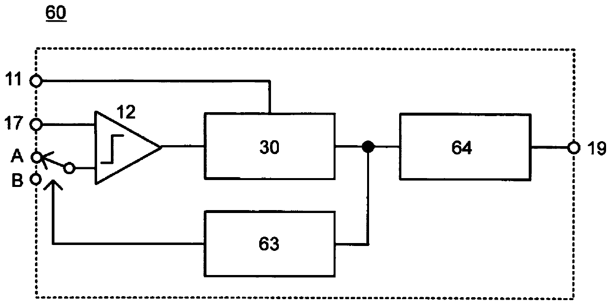
[0139] figure 1 The A / D converter 60 according to the first embodiment of the present disclosure is shown. The A / D converter 60 according to the first embodiment includes a comparator 12, an internal A / D converter 30, a reference voltage selection circuit 63, and an accumulation adder-subtractor 64, wherein the reference voltage selection circuit 63 has two kinds of ramp signals Serving as a reference voltage and switching between the reference voltages, the accumulative adder-subtractor 64 is used to perform accumulative addition or accumulative subtraction on a plurality of converted values and output the averaged output as an A / D converted value.
[0140] In the A / D converter 60 according to the first embodiment, the comparator 12 compares the pixel signal with the ramp signal as the reference voltage signal, generates a comparison output at the time when the two signals intersect, and controls the counter to ...
no. 2 approach
[0194] (A time-domain A / D conversion module including multiple A / D converters using a multi-phase clock formed by a DLL circuit)
[0195] Figure 14 A time-domain A / D conversion module including a plurality of A / D converters according to an embodiment of the present disclosure is shown. The A / D conversion module 10 includes a DLL (delay locked loop) circuit 20, and also includes a plurality of comparators 12-1, 12-2, ..., 12-n (n is a natural number, hereinafter, without distinguishing each comparator 12) and a plurality of internal A / D converters 30-1, 30-2, . A plurality of A / D converters 14-1, 14-2, . / D converter 14).
[0196] The DLL circuit 20 includes a plurality of delay circuits 21-1, 21-2, 21-3, and 21-4 (hereinafter referred to as delay circuits 21 when the respective delay circuits are not distinguished), a phase comparator (PD) 22, a charge pump (CP) and low pass filter (LPF) 23 . Four-stage delay circuits 21 - 1 , 21 - 2 , 21 - 3 , and 21 - 4 arranged in ser...
no. 3 approach
[0207] (conversion from polyphase clock signal to Gray code)
[0208] Figure 17 An A / D conversion module according to a third embodiment of the present disclosure is shown. The A / D conversion module 90 according to the third embodiment differs from the A / D conversion module 10 according to the second embodiment in that it further includes a Gray circuit between the DLL circuit 20 and the internal A / D converter 30 Code converter 50. The same description as the second embodiment is omitted, and the parts different from the A / D conversion module 10 according to the second embodiment are described here.
[0209] The Gray code converter 50 converts the multiphase clock signal 15 output from the DLL circuit 20 from a thermometer code (thermometric code) into a Gray code, and then inputs it to a latch or a trigger of a TDC unit constituting each internal A / D converter 30. Device 31. By configuring in this way, the number of latches constituting the TDC can be greatly reduced, an...
PUM
 Abstract
Description
Claims
Application Information