
Ultrafine particle separation system under coupling mechanism

A technology of ultra-fine particles and separation systems, applied in the direction of dispersion particle separation, separation methods, chemical instruments and methods, etc., can solve problems such as rising costs and high maintenance frequency, and achieve convenient matching, simple combination, and low processing complexity. low cost effect

Pending Publication Date: 2020-08-21
CHINA UNIV OF PETROLEUM (EAST CHINA)
View PDF10 Cites 5 Cited by
  • Summary
  • Abstract
  • Description
  • Claims
  • Application Information

AI Technical Summary

Problems solved by technology

However, when the existing turbulence coalescing device is applied to the cyclone separator to achieve ultrafine particle separation, in order to achieve higher separation efficiency, it is often necessary to enhance the coalescence effect with electric field force to achieve a higher separation effect, which often brings The additional increase of other costs, such as the increase of the electric field, greatly increases the power consumption, and requires a complex power control system, which increases the cost and the frequency of maintenance. Pursue the turbulent flow of a single mechanical structure and apply it to the cyclone separator to achieve the purpose of efficiently separating ultrafine particles

Method used


Image

  • Ultrafine particle separation system under coupling mechanism
  • Ultrafine particle separation system under coupling mechanism
  • Ultrafine particle separation system under coupling mechanism

Examples


Embodiment Construction

[0028]The technical solutions in the embodiments of the present invention will be described in more detail below in conjunction with the accompanying drawings in the embodiments of the present invention. Obviously, the described embodiments are only part of the embodiments of the present invention, not all embodiments. These embodiments are provided to illustrate the present invention more clearly and fully convey the scope of the present invention to those skilled in the art.

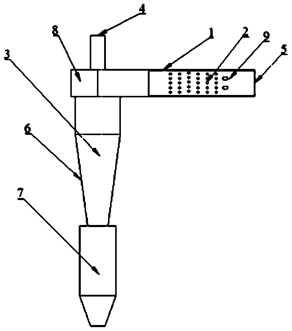
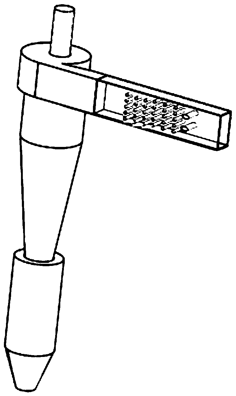
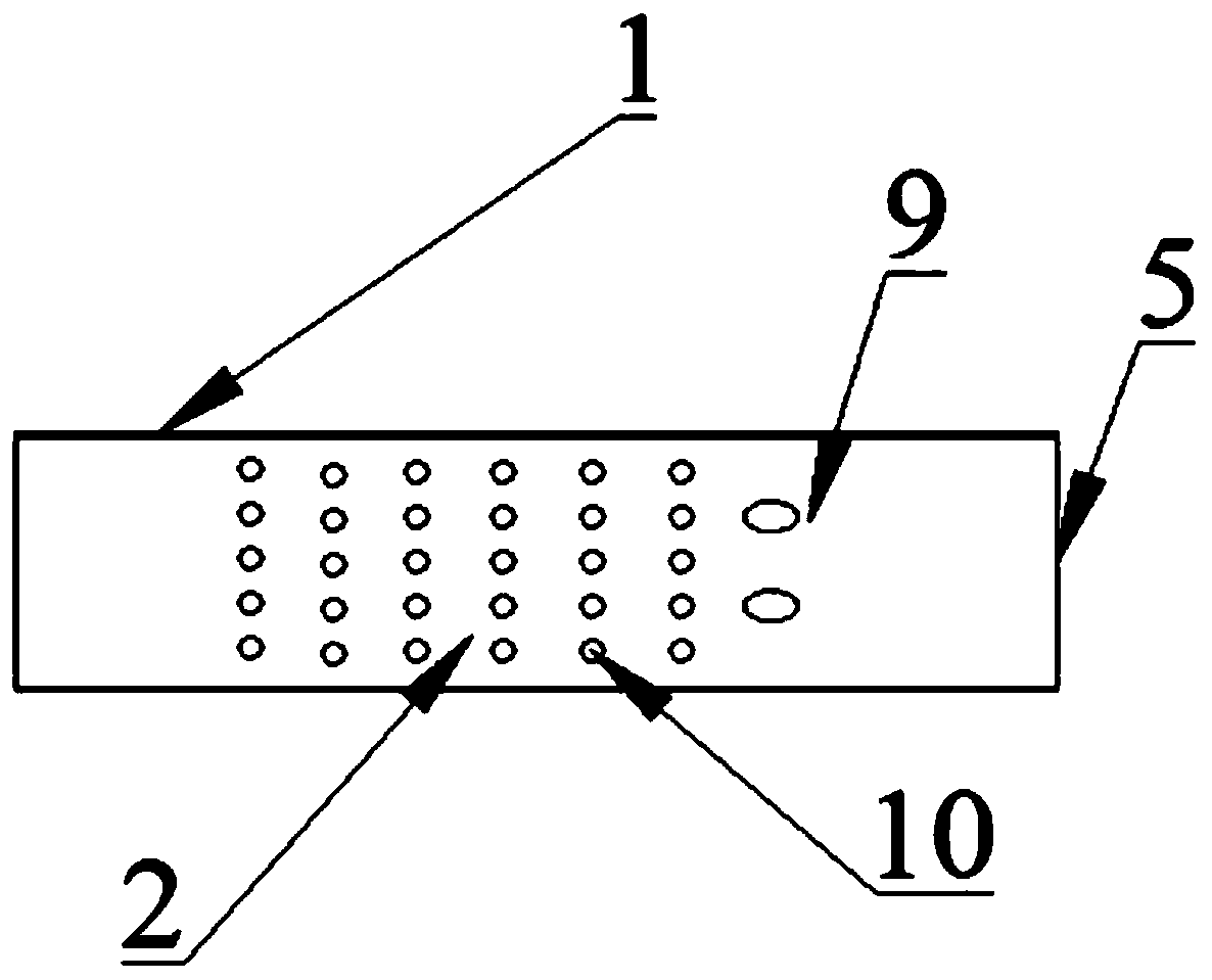
[0029] Reference attached figure 1 And attached figure 2 , figure 1 It is a two-dimensional schematic diagram of the ultrafine particle separation system under the coupling mechanism, figure 2 A three-dimensional schematic diagram of an ultrafine particle separation system under a coupling mechanism, an ultrafine particle separation system under a coupling mechanism of the present invention includes a separation device cyclone separator 3 and a turbulence coalescer 1 . Below the cyclone separator ...


PUM

PropertyMeasurementUnit
dust removal efficiencyaaaaaaaaaa

Abstract

The invention aims to provide an ultrafine particle separation system under a coupling mechanism. A turbulence coalescer of a pure mechanical structure and cyclone separation equipment are directly and sequentially installed together, efficient separation of ultrafine particles is achieved by means of a coupling mechanism, the ultrafine particle separation effect is good, and the system is simplein structure, safe and reliable in equipment, wide in application range, and suitable for various ultrafine particle separation processes. The system comprises a cyclone separator, the turbulence coalescer is arranged at an inlet of the cyclone separator, the turbulence coalescer comprises a shell, the shell comprises an inlet and an outlet, the outlet of the shell is connected with the inlet of the cyclone separator, the cross section of the shell is rectangular, a turbulence column device is arranged in the shell, and a plurality of guide vanes are further arranged in the upstream directionof the turbulence column device.

Description

technical field [0001] The invention relates to the technical field of particle separation, in particular to an ultrafine particle separation system under a coupling mechanism. Background technique [0002] At present, many industrial processes will produce a large number of fly ash particles, such as the power generation process of coal-fired power plants, catalytic cracking process and so on. These fly ash particles can be collected by various forms of conventional dust removal equipment, such as electrostatic precipitators, baghouses, cyclones and wet dust collectors. Among them, the cyclone separator has become the preferred equipment for this process due to its advantages of simple design, cheap manufacture, low maintenance cost, and wide adaptability to operating conditions. However, these conventional dust removal equipment are not effective in collecting ultrafine particles. For example, the mass dust removal efficiency of high-efficiency electrostatic precipitators...

Claims


Application Information

Patent Timeline
Patent Type & Authority Applications(China)
IPC IPC(8): B01D45/14
CPCB01D45/14
Inventor 许伟伟张猛原欣梁东伟李强
Owner CHINA UNIV OF PETROLEUM (EAST CHINA)
Learn More