Wear-resistant guide plate and laser remanufacturing process thereof

A guide plate and process technology, which is applied in the direction of manufacturing tools, metal material coating process, metal rolling, etc., can solve the problems of easy wear, reduced work efficiency, excessive thermal stress, etc., to reduce the cost of use and improve the service life , to avoid the effect of hardness drop

Active Publication Date: 2020-08-21
成都大陆激光技术有限公司
View PDF12 Cites 0 Cited by
  • Summary
  • Abstract
  • Description
  • Claims
  • Application Information

AI Technical Summary

Problems solved by technology

[0002] like figure 1 Shown is the roller table part of steel plate transportation in the rolling process, mainly including: driving device 1, moving roller 2, guide arm 3, the driving device 1 is located at both ends of the roller table, driving the moving roller 2 to rotate, and after a The rolled steel plate will move forward with the rotation of the rotating roller. In order to prevent the movement of the steel plate from deviating from the direction, guide arms 3 are arranged on both sides of the moving roller 2. The angle of the guide arm 3 can be adjusted to limit the direction of movement of the steel plate. , but because the temperature of the steel plate during the rolling process is very high, and the friction force between the guide arm 3 and the guide arm 3 is relatively large during the movement, it will cause a groove to be worn out on the part of the guide arm 3 and the steel plate that often contacts. It is uneven, so the guide arm 3 that wears to a certain extent can no longer be used, and under normal circumstances, the daily output of a medium and large steel rolling mill can at least reach the production capacity of millions of tons, such a large workload will lead to The guide arm 3 needs to be replaced frequently, and the production line needs to be stopped every time it is replaced, which reduces the work efficiency in a disguised form and increases the cost of use. In order to solve this problem, the existing technology mainly adopts more wear-resistant material or surface processing
[0003] Laser remanufacturing technology is an advanced surface processing technology that integrates cladding processing, laser cladding material technology and other technologies. It can not only restore the shape of damaged parts, but also make its performance reach or even exceed that of new products. level, and the cost of laser remanufacturing is only 50% of the cost of new products, and energy saving is 60%. Among them, laser cladding is the most widely used one. Laser cladding refers to placing selected coating materials with different fillers on the surface of the coated substrate, and irradiating them with laser The surface of the substrate is melted at the same time, and after rapid solidification, a coating with extremely low dilution and metallurgical bonding with the substrate metal is formed. However, due to the small laser spot, the volume of the molten pool formed is also small, so it cools faster, which is typical In the process of rapid heating and rapid cooling, excessive thermal stress will be generated during the cladding process, which increases the possibility of crack defects in subsequent use
[0004] The method of strengthening by laser coating is more commonly used. For example, the invention patent with the authorized announcement number CN105779925B discloses "A Method for Laser Coating by Supersonic Flame Spraying Preset Powder", which discloses the method of laser coating by supersonic flame spraying. The method of combining sonic flame spraying and laser cladding can alleviate the problem of rapid cooling and rapid heating in the laser cladding process through pretreatment, so it can provide a refined laser cladding layer structure and improve the quality of the laser cladding layer, but this method It is not suitable for wear-resistant guide plates, because the use environment of the guide plate is relatively harsh, the ambient temperature is high, the higher the temperature of the guide plate, the hardness will decrease, so it cannot achieve the best use in the guide plate effect, and the steel rolling production line is often running 24 hours a day, and it will only stop when it is overhauled. Therefore, the longer the use time, the higher the temperature, and the easier it is to wear. Therefore, the existing technology is not suitable for use in guided laser remanufacturing. in process

Method used


Image

  • Wear-resistant guide plate and laser remanufacturing process thereof
  • Wear-resistant guide plate and laser remanufacturing process thereof
  • Wear-resistant guide plate and laser remanufacturing process thereof

Examples


Embodiment 1

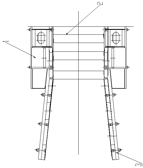
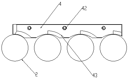
[0041] Such as Figure 2~3 Shown is a wear-resistant guide plate, which is used to solve the problem that the bottom of the guide arm in the prior art is worn and cannot be used and can only be replaced, which affects production efficiency and increases the cost of use. In addition, it also includes a guide plate 4, which is detachably installed at the bottom of the guide arm to replace the part of the guide arm that originally rubs against the steel plate. Due to the detachable connection, compared with replacing the entire guide arm, the replacement speed is faster , has the least impact on production efficiency. Furthermore, the surface treatment of the guide plate 4 is carried out through the laser reprocessing process to increase the hardness of the surface. To continue to use, thereby prolonging the service life and reducing the frequency of replacement; in addition, compared with other thermal cladding technologies, laser reprocessing has lower energy consumption and mo...

Embodiment 2

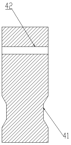
[0045] The difference between this embodiment and the previous embodiment is that a cooling channel 45 is provided in the axial direction of the guide plate 4, such as Figure 4 As shown, the cross-sectional shape of the cooling channel 45 is I-shaped, and the volume of the upper and lower parts is relatively large, which can store more water. The cold water flows into the cooling channel 45 from the bottom, and flows out from the top surface of the cooling channel 45, forming A channel, through the flow of water to take away the heat during use, so that the guide plate 4 is always at a lower temperature, avoiding the temperature rise of the guide plate 4 due to contact with the uncooled steel plate, and the high temperature will cause the hardness of the guide plate 4 to decrease. more prone to wear and tear.

[0046] Further, threaded holes are evenly arranged on the cladding groove 41, the threaded holes are arranged horizontally, and pass through the surface of the cooling...

experiment example 1

[0061] Experimental Example 1: Microhardness Test

[0062] Experimental sample:

[0063] a: The base material is the guide plate of 16Mn;

[0064] b: The base material is 16Mn, and the structure of the workpiece is as described in Example 1. On the basis of the original workpiece, the process of the prior art is used to process the cladding groove part of it by laser cladding to prepare a layer Wear-resistant metal layer;

[0065] c: the base material is 16Mn, the workpiece structure is as described in Example 2, and is processed by the above-mentioned steps;

[0066] The metal used for cladding is tungsten carbide alloy powder, the main components are W8%, Mo10%, Ni15%, Cr6%, Fe balance;

[0067] Process parameters of laser cladding: semiconductor laser is used; laser power is 3000W, scanning speed is 1000mm / min, and spot is square: 3*8mm.

[0068] Experimental equipment: HV-1000 microhardness tester.

[0069] experimental method:

[0070] Select the test force and turn...


PUM


Abstract

The invention discloses a wear-resistant guide plate, and is used to solve the problem that the bottom of a guide arm cannot be used after being worn out in the prior art, and can only be replaced, thereby affecting the production efficiency and increasing the use cost. The wear-resistant guide plate comprises the guide arm, and further comprises a guide plate. The guide plate is detachably installed at the bottom of the guide arm to replace the original friction part between the guide arm and a steel plate. Because of the detachable connection, the replacement speed is faster than replacing the entire guide arm and the impact on production efficiency is minimal. Furthermore, the surface treatment of the guide plate through laser remanufacturing process increases the surface hardness. At the same time, during the processing, the two sides of the guide plate have the same structure and can be used directly by turning over, thereby prolonging the service life and reducing the frequency of replacement. In addition, compared with other thermal cladding technologies, the laser remanufacturing process consumes lower energy and more concentrated heat and can improve processing efficiency.

Description

technical field [0001] The invention belongs to the technical field of laser reprocessing, and in particular relates to a wear-resistant guide plate and a laser remanufacturing process thereof. Background technique [0002] Such as figure 1 Shown is the roller table part of steel plate transportation in the rolling process, mainly including: driving device 1, moving roller 2, guide arm 3, the driving device 1 is located at both ends of the roller table, driving the moving roller 2 to rotate, and after a The rolled steel plate will move forward with the rotation of the rotating roller. In order to prevent the movement of the steel plate from deviating from the direction, guide arms 3 are arranged on both sides of the moving roller 2. The angle of the guide arm 3 can be adjusted to limit the direction of movement of the steel plate. , but because the temperature of the steel plate during the rolling process is very high, and the friction force between the guide arm 3 and the ...

Claims


Application Information

Patent Timeline
Patent Type & Authority Applications(China)
IPC IPC(8): B21B39/02C23C24/10B23P6/00
CPCB21B39/02C23C24/103B23P6/00
Inventor 齐海红刘作彩张岿然周岳平
Owner 成都大陆激光技术有限公司
Why Eureka
Try Eureka