
Drill rod machining automatic feeding system and method

A technology of automatic feeding and drilling, applied in metal processing, automatic control devices, metal processing equipment, etc., can solve the problems of heavy weight (weight over 30Kg, long length, etc., to save the floor space of workshop equipment, improve production Efficiency and the effect of ensuring the success rate of material distribution

Active Publication Date: 2020-08-25
XIAN RES INST OF CHINA COAL TECH& ENG GROUP CORP
View PDF8 Cites 9 Cited by
  • Summary
  • Abstract
  • Description
  • Claims
  • Application Information

AI Technical Summary

Problems solved by technology

[0003] Aiming at the defects and deficiencies in the prior art, the present invention provides an automatic feeding system and method for drill pipe processing to solve the problem of drilling pipes with relatively long length (more than 2 meters in length) and relatively heavy weight (more than 30Kg in weight). The problem of automatic feeding when CNC machining is performed on the machine tool

Method used


Image

  • Drill rod machining automatic feeding system and method
  • Drill rod machining automatic feeding system and method
  • Drill rod machining automatic feeding system and method

Examples


Embodiment 1

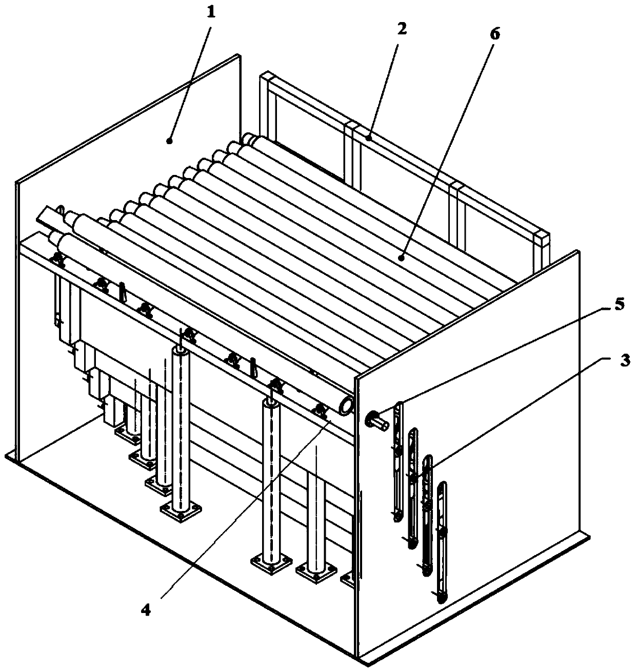
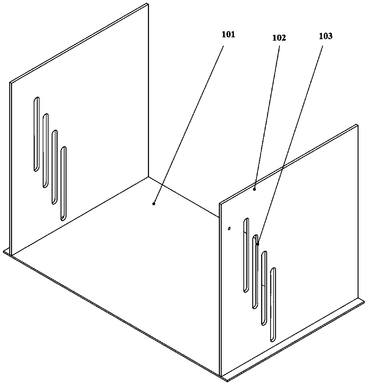
[0059] Such as Figure 1 to Figure 9 As shown, this embodiment provides an automatic feeding system for drill pipe processing, including a frame 1, a drill pipe box 2, a step material distribution device 3, a buffer device 4 and a positioning device 5; the frame 1 includes a frame bottom plate 101 And the two frame side plates 102 that are vertically fixed on the two ends of the frame bottom plate 101 and are parallel to each other; Between, and the above-mentioned components are equipped with sensors.

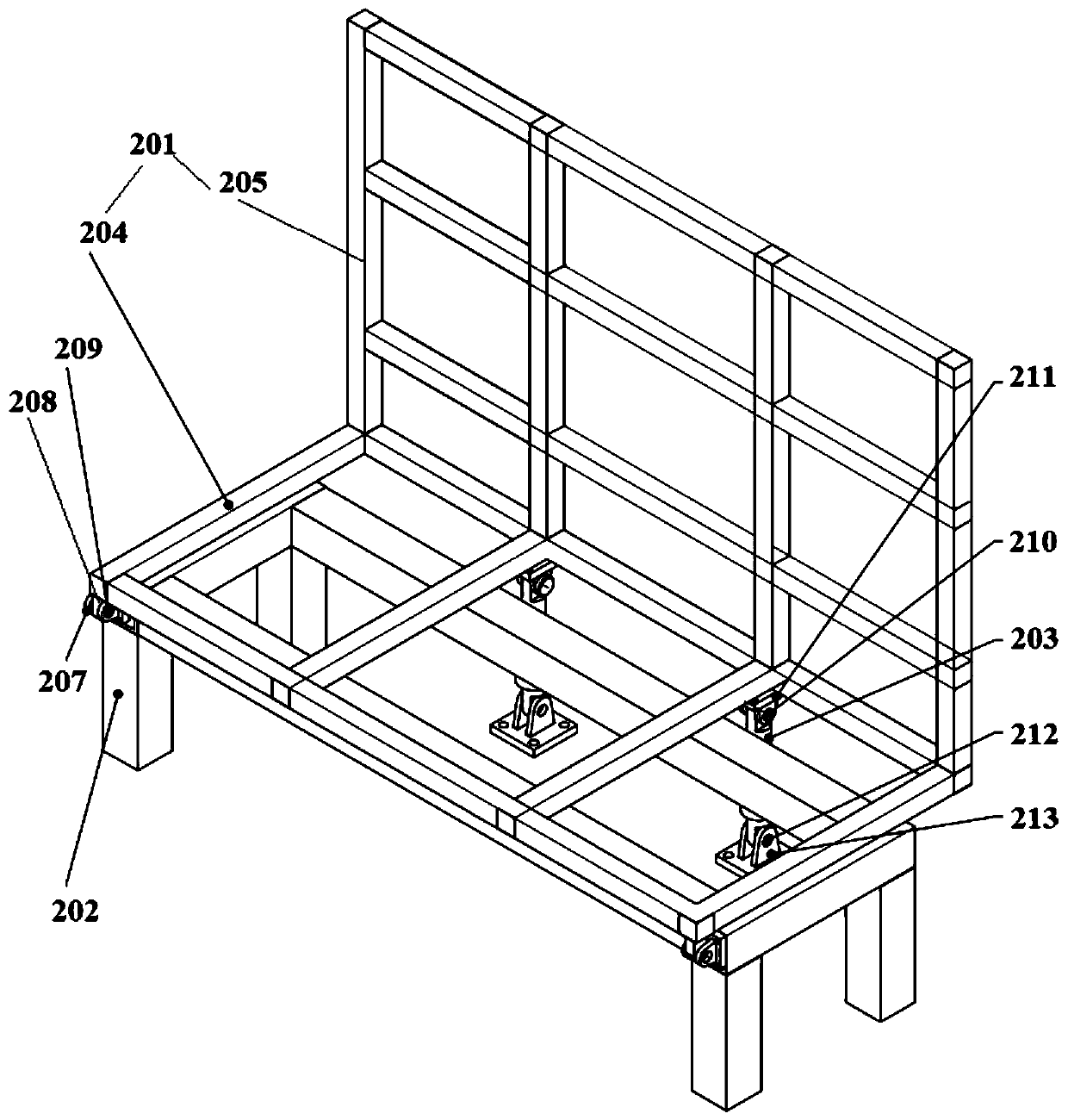
[0060] Drill rod case 2 comprises hopper 201, is located at the drill rod support 202 of hopper 201 below and tilts oil cylinder 203; Inside the hopper 201 and parallel to the bottom frame 204 and the side frame 205; the two sides of the bottom frame 204 are the hinged side and the jacking side respectively, the hinged side is hinged with the drill pipe support 202 below it, and the upper end of the jacking side is a side frame 205, which can be lifted The bottom of the side...

Embodiment 2

[0088] This embodiment provides a control method for an automatic feeding system for drill pipe processing, including the following steps:

[0089] Step 1, unloading: hoist the entire drill pipe into the drill pipe box manually, and the height of the drill pipe should not exceed the buffer device;

[0090] Step 2, the action of the one-level step material distribution unit: when the buffer device sensor detects that there is no drill pipe on the buffer device, and the first-level step sensor detects that there is a drill pipe, the material distribution jacking cylinder that controls the first-level step material distribution unit starts the first step. For one jacking action, stay at the highest point for 2 seconds to ensure that the drill pipe rolls down to the buffer device due to gravity along the slope of the first step material distribution unit, and the first step material distribution unit falls, and this process is completed once. A single drill pipe works separately f...


PUM


Abstract

The invention discloses a drill rod machining automatic feeding system and method. The system comprises a rack, a drill rod box, a stepped distributing device, a buffer device and a positioning device. Sensors are arranged on the parts. The system achieves the functions of drill rod automatic distributing and discharging functions during drill rod machining, the labor intensity of workers can be effectively reduced through a stable and reliable automatic feeding system, the production efficiency is improved, and meanwhile the safety risk probably caused during work of the workers is reduced. According to the method, through mutual cooperation and cooperative work of the graded stepped distributing device, the drill rod box, the positioning device, the buffer device and a sensor detection system, single drill rods are independently separated from the drill rod box and positioned, and distributing and discharging automation of the drill rods is achieved; and a multi-step automatic discharging method is adopted, so that the problem about automatic feeding generated when the long and heavy drill rods are subjected to numerical control machining on a machine tool is solved.

Description

technical field [0001] The invention belongs to the technical field of drill pipe machining, and in particular relates to an automatic feeding system for drill pipe processing and an automatic feeding method for drill pipe processing. Background technique [0002] At present, in the domestic drilling pipe turning process, manual loading is mainly used, and workers have frequent labor operations and high labor intensity; secondly, manual loading has great potential safety hazards, and safety production accidents are prone to occur, and production safety performance is low; The automatic continuous processing of the drill pipe cannot be realized by manual feeding, and the production efficiency is low. At present, the mainstream uses a manipulator mechanism for automatic feeding, but this mechanism is relatively complicated and expensive, and it is not suitable for drill pipes with a relatively long length (more than 2 meters in length) and a relatively heavy weight (over 30Kg)...

Claims


Application Information

Patent Timeline
Patent Type & Authority Applications(China)
IPC IPC(8): B23Q7/12B23Q15/00B65G47/08
CPCB23Q7/12B23Q15/00B65G47/088
Inventor 董萌萌田东庄路前海赵飞鄢忠方吕孟
Owner XIAN RES INST OF CHINA COAL TECH& ENG GROUP CORP
Learn More