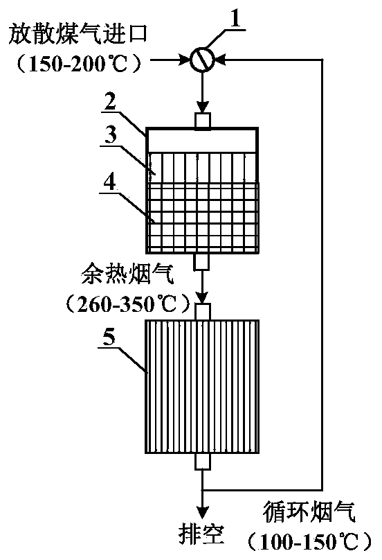
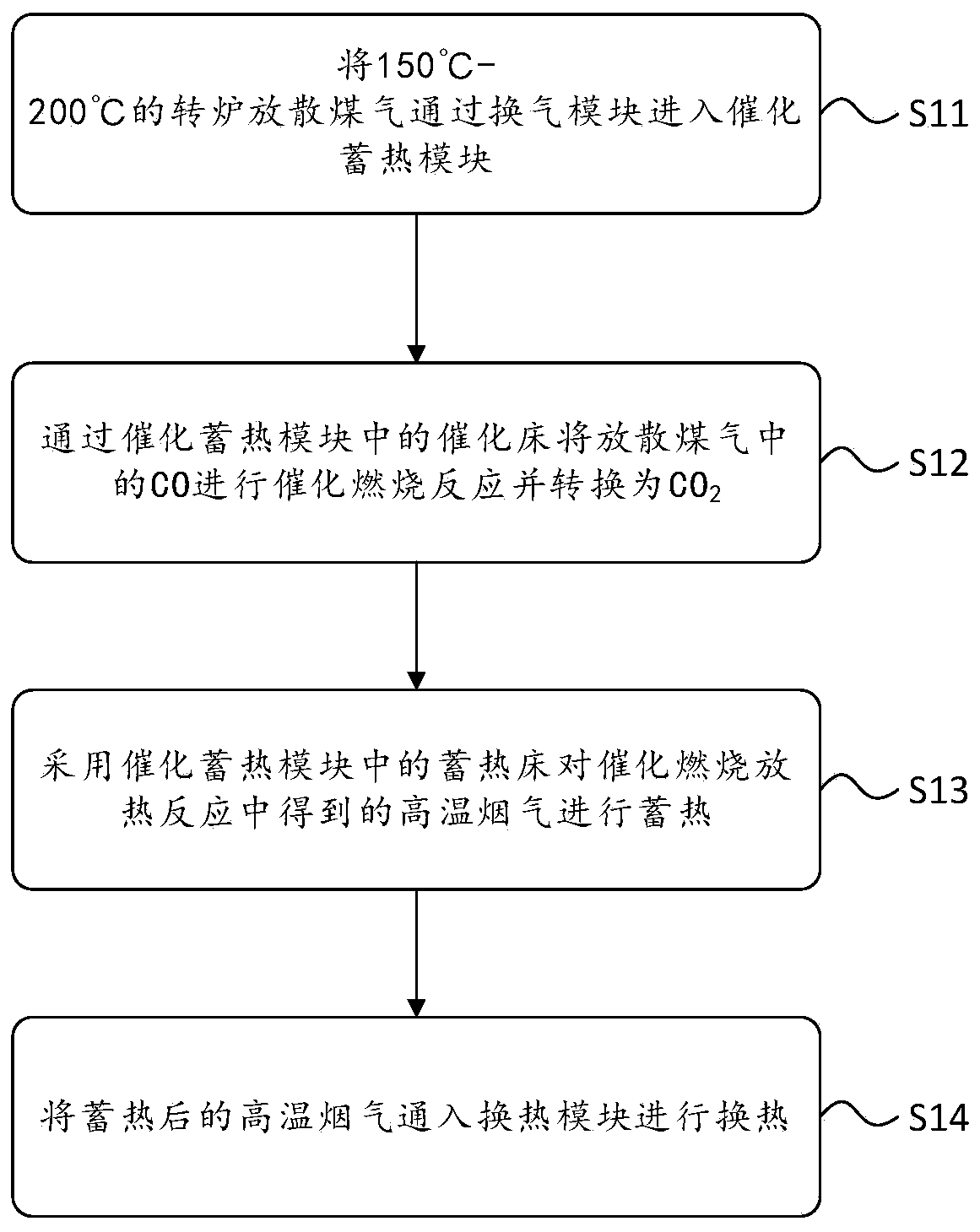
Converter-diffused coal gas catalyzing and heat-storage integration and heat-exchanging system, and method

A technology of gas release and heat exchange system, which is applied in the direction of combustion method, incinerator, lighting and heating equipment, etc., and can solve the problem of unseen honeycomb ceramic catalyst catalytic combustion-heat storage integration, high-efficiency heat exchange method, complex equipment, etc. To achieve the effect of improving waste heat utilization quality, low operating cost, simple and safe operation

Inactive Publication Date: 2020-08-25
INST OF MECHANICS - CHINESE ACAD OF SCI
View PDF6 Cites 3 Cited by
  • Summary
  • Abstract
  • Description
  • Claims
  • Application Information

AI Technical Summary

Problems solved by technology

Chinese patent, authorized announcement number CN105642108B, discloses a method for CO recovery and treatment in the metallurgical industry. The method uses low-temperature plasma to couple Cu-based composite oxide catalysts to process CO, which can realize CO catalytic combustion under low temperature conditions, but the plasma The method and equipment are more complex
[0004] At present, there are few relevant reports on the comprehensive utilization technology of metallurgical waste gas, especially intermittent converter gas. At the same time, there are no reports on the integration of catalytic combustion and heat storage of honeycomb ceramic catalysts and high-efficiency heat transfer methods in the open literature. Therefore, , there is an urgent need to develop a catalytic and heat storage integrated device and heat exchange system for blown gas from the converter, so as to provide a new technology for the clean utilization of the blown gas in the converter and the recovery of waste heat

Method used


Image

  • Converter-diffused coal gas catalyzing and heat-storage integration and heat-exchanging system, and method
  • Converter-diffused coal gas catalyzing and heat-storage integration and heat-exchanging system, and method

Examples


Embodiment Construction

[0024] In order to make the purpose, technical solutions and advantages of the embodiments of the present invention more clear, the following will clearly and completely describe the technical methods in the embodiments of the present invention in conjunction with the accompanying drawings in the embodiments of the present invention. Obviously, the described embodiments It is only some embodiments of the present invention, but not all embodiments. Based on the embodiments of the present invention, all other embodiments obtained by persons of ordinary skill in the art without making creative labor achievements belong to the protection scope of the present invention.

[0025] It should be noted that if there is a directional indication (such as up, down, left, right, front, back, etc.) in the embodiment of the present invention, the directional indication is only used to explain the relationship between the components in a certain posture. Relative positional relationship, movem...


PUM


Abstract

The embodiments of the invention relate to a converter-diffused coal gas catalyzing and heat-storage integration and heat-exchanging system, and a method. The converter-diffused coal gas catalyzing and heat-storage integration and heat-exchanging system comprises a ventilation module, a catalyzing and heat-storage module and a heat-exchanging module which are arranged on a pipeline in sequence; the ventilation module is connected with the catalyzing and heat-storage module and introduces diffused coal gas into the catalyzing and heat-storage module to enable the diffused coal gas to be subjected to a catalytic combustion exothermic reaction in the catalyzing and heat-storage module so as to convert CO in the diffused coal gas into CO2, and meanwhile heat storage is conducted on high-temperature smoke obtained in the catalytic combustion exothermic reaction; and the catalyzing and heat-storage module is connected with the heat-exchanging module, and the high-temperature smoke is introduced into the heat-exchanging module for heat exchanging. The method has the characteristics of low operation cost, high catalytic efficiency, high waste heat recycling rate, easy and safe operation and the like; and by adopting the method to treat the diffused coal gas, the national or regional emission standard can be met, meanwhile heat is recycled in a heat-storage mode, the waste heat utilization quality is improved, and energy conservation and emission reduction are achieved.

Description

technical field [0001] The embodiments of the present invention relate to the technical field of converter blow-off gas treatment, in particular to a converter blow-off gas catalysis and heat storage integration and heat exchange system. Background technique [0002] A large amount of converter gas will be produced in the converter steelmaking process, and the efficient recovery and heat recovery of converter gas are the key to realize negative energy converter steelmaking. Converter steelmaking is mainly divided into three stages: the early stage, the middle stage and the end stage of steelmaking. In the middle stage of steelmaking, the oxygen content of the converter gas is low (<1-3%) and the CO concentration is high (>35%). Recovery; while in the early and late stages of steelmaking, converter gas has high oxygen content (>3%) and low CO concentration (<35%), which does not meet the gas recovery standards, and is usually discharged by direct combustion, and t...

Claims


Application Information

Patent Timeline
Patent Type & Authority Applications(China)
IPC IPC(8): F23G7/07F23G5/46
CPCF23G5/46F23G7/07F23G2202/60F23G2206/20F23G2209/14F23G2900/00001
Inventor 魏小林康润宁宾峰李博姚远何浚珧
Owner INST OF MECHANICS - CHINESE ACAD OF SCI
Why Eureka
Try Eureka