A flue gas waste heat recovery system

A recovery system and flue gas waste heat technology, applied in the direction of heat recovery system, heating system, hot water central heating system, etc., can solve the problems of difficult to effectively match the heat exchange temperature difference, energy waste, large heat pump equipment investment, etc., to achieve reduction Irreversible heat transfer loss, reduced investment, and improved efficiency

Active Publication Date: 2022-08-09
北京热科能源技术研究有限公司
View PDF1 Cites 0 Cited by
  • Summary
  • Abstract
  • Description
  • Claims
  • Application Information

AI Technical Summary

Problems solved by technology

This setting results in a large temperature difference at the heat exchange end on the high-temperature side of the flue gas. A part of the high-temperature flue gas heat first enters the low-temperature medium and then enters the circulation, and then is driven by the heat pump to drive the heat source to extract water for the heating network, resulting in waste of energy. At the same time lead to a larger investment in heat pump equipment
In addition, during the cooling process of the flue gas, as the water vapor condenses, the specific heat capacity changes greatly, while the specific heat capacity of the spray water remains almost unchanged. If the flow rate of the spray water does not change, the heat exchange temperature difference between the two fluids Difficult to match effectively, also caused relatively large irreversible heat transfer loss

Method used


Image

  • A flue gas waste heat recovery system
  • A flue gas waste heat recovery system
  • A flue gas waste heat recovery system

Examples


Embodiment Construction

[0025] In order to make the objectives, technical solutions and advantages of the present invention clearer, the present invention will be further described in detail below with reference to the specific embodiments and the accompanying drawings. It should be understood that these descriptions are exemplary only and are not intended to limit the scope of the invention. Also, in the following description, descriptions of well-known structures and techniques are omitted to avoid unnecessarily obscuring the concepts of the present invention.

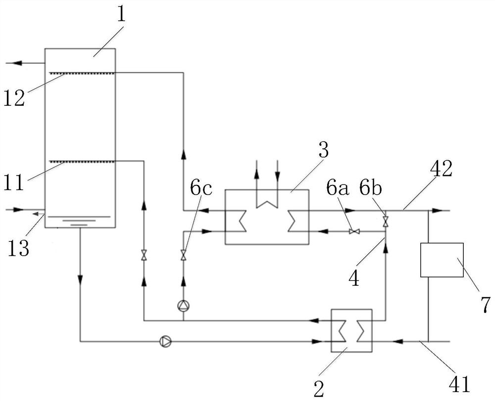
[0026] figure 1 It is a schematic diagram of the first implementation structure provided by the present invention.

[0027] like figure 1 As shown, a flue gas waste heat recovery system provided in this embodiment includes: a first heat exchanger 1 , a second heat exchanger 2 , a heat pump 3 and a heat network pipeline 4 .

[0028] The first heat exchanger 1 is a direct contact heat exchanger with a cavity structure in the form of a spra...


PUM


Abstract

The invention discloses a flue gas waste heat recovery system, comprising: a first heat exchanger, a second heat exchanger, a heat pump and a heat network pipeline; the first heat exchanger is provided with a first liquid distribution device and a second liquid distribution device device; the bottom of the first heat exchanger is communicated with the input end of the heat release side of the second heat exchanger; the output end of the heat release side of the second heat exchanger is communicated with the first liquid distribution device to form a first fluid circulation loop; The output end of the heat release side of the second heat exchanger is also communicated with the heat pump and the second liquid distribution device in sequence to form a second fluid circulation loop; the heat network pipeline includes a heat network return water pipeline and a heat network water supply pipeline; the heat network pipeline is connected with The heat absorption side of the second heat exchanger is connected to form a heat network circulation loop; and / or the heat network pipeline is sequentially connected with the heat absorption side of the second heat exchanger and the heat pump to form a heat network water circulation loop. This setting can improve the recovery efficiency of waste heat from flue gas and reduce investment in heat pump equipment.

Description

technical field [0001] The invention relates to the technical field of waste heat recovery, in particular to a flue gas waste heat recovery system. Background technique [0002] Natural gas flue gas contains a large amount of water vapor, and the condensation heat carried by this part of the water vapor accounts for about 10% of the low-level calorific value of natural gas, which is an important factor affecting the utilization efficiency of natural gas. Therefore, recovering this part of the condensation heat can significantly improve Thermal efficiency of natural gas. [0003] The prior art discloses a central heating system (CN102242946B) that uses an absorption heat pump to recover the waste heat of flue gas, and uses a combination of a flue gas-water direct contact heat exchanger and an absorption heat pump to recover the heat of the flue gas. At the same time, it can also reduce the concentration of nitrogen oxides in the exhaust gas to a certain extent. However, in ...

Claims


Application Information

Patent Timeline
Patent Type & Authority Patents(China)
IPC IPC(8): F23J15/06F24D3/18
CPCF23J15/06F24D3/18F24D2200/18Y02E20/30
Inventor 张世钢
Owner 北京热科能源技术研究有限公司
Why Eureka
Try Eureka