
A High Field In Situ Polarization Method Using Parahydrogen Induced Polarization

An in-situ, high-field technology, applied in the field of magnetic resonance spectroscopy, can solve the problems of unsatisfactory application requirements, heavy equipment, loss of polarization signals, etc., and achieve the effects of easy production and maintenance, simple operation, and uniform and stable magnetic field

Active Publication Date: 2022-05-03
INNOVATION ACAD FOR PRECISION MEASUREMENT SCI & TECH CAS
View PDF8 Cites 0 Cited by
  • Summary
  • Abstract
  • Description
  • Claims
  • Application Information

AI Technical Summary

Problems solved by technology

At present, there is no corresponding device design in China to meet the needs. The existing high-field in-situ polarization technology in foreign countries has poor magnetic field stability, which affects the quality of the spectrum, and NMR sampling has a certain delay, resulting in the loss of polarization signals. , to reduce the signal strength, and the instrument device is relatively bulky, which cannot meet the application requirements in a specific environment

Method used


Image

  • A High Field In Situ Polarization Method Using Parahydrogen Induced Polarization
  • A High Field In Situ Polarization Method Using Parahydrogen Induced Polarization
  • A High Field In Situ Polarization Method Using Parahydrogen Induced Polarization

Examples


Embodiment 1

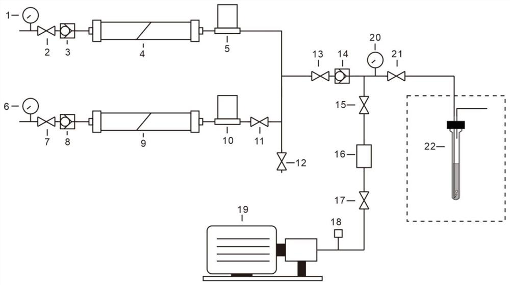
[0039] A high-field in-situ polarization device using parahydrogen-induced polarization, including a vacuum pump 19, including a parahydrogen inlet channel, a reaction gas inlet channel and a reaction sampling tube 22,

[0040]The outlet end of the reaction gas inlet channel is connected to one end of the third through valve 11, and the other end of the third through valve 11 is respectively connected to the outlet end of the parahydrogen inlet channel, one end of the fourth through valve 12 and one end of the fifth through valve 13, The other end of the fifth through valve 13 is connected to the inlet end of the third one-way valve 14, and the outlet end of the third one-way valve 14 is respectively connected to one end of the eighth through valve 21 and one end of the sixth through valve 15, and the eighth through valve 21 The other end is connected to the reaction sampling pipe 22, the other end of the sixth through valve 15 is connected to the vacuum pump 19 through the vac...


PUM

PropertyMeasurementUnit
diameteraaaaaaaaaa

Abstract

The invention discloses a high-field in-situ polarization device using parahydrogen-induced polarization. The outlet end of the reaction gas inlet channel is connected to one end of a third through valve, and the other end of the third through valve is respectively connected to the parahydrogen inlet channel. The outlet end of the fourth through valve is connected to one end of the fifth through valve, the other end of the fifth through valve is connected to the inlet end of the third one-way valve, and the outlet end of the third one-way valve is connected to one end of the eighth through valve and one end of the eighth through valve respectively. One end of the sixth straight-through valve is connected, the other end of the eighth straight-through valve is connected to the reaction sampling pipe, the other end of the sixth straight-through valve is connected to the vacuum pump through the vacuum chamber, the seventh straight-through valve, and the vacuum gauge in sequence, and the eighth straight-through valve is connected to the third one-way valve. A third pressure gauge is arranged at one end connected to the outlet of the valve, and the reaction sampling tube is placed in the nuclear magnetic resonance magnet. The invention also discloses a high-field in-situ polarization method utilizing parahydrogen-induced polarization. The invention has the advantages of simple structure, convenient control and operation, and realizes efficient polarization generation and stable polarization nuclear magnetic spectrum signal collection.

Description

technical field [0001] The present invention relates to the technical field of magnetic resonance spectroscopy, more specifically to a high-field in-situ polarization device utilizing parahydrogen-induced polarization, and to a high-field in-situ polarization method utilizing parahydrogen-induced polarization . It is suitable for in-situ reaction system nuclear magnetic resonance polarization technology in high magnetic field environment with parahydrogen gas as the polarization source, such as gas-solid reaction system, gas-liquid reaction system, gas-liquid-solid reaction system, etc. Background technique [0002] NMR technology (Nuclear Magnetic Resonance, NMR) can give key information on material components, molecular structures and related dynamics. It is a very important research method and analysis method. It is currently used in many fields such as biology, chemistry, medicine and physics. have a wide range of applications. The nuclear magnetic signal intensity is ...

Claims


Application Information

Patent Timeline
Patent Type & Authority Patents(China)
IPC IPC(8): G01R33/30G01R33/46G01N24/08
CPCG01R33/30G01R33/46G01N24/08G01N24/087
Inventor 王伟宇徐君邓风
Owner INNOVATION ACAD FOR PRECISION MEASUREMENT SCI & TECH CAS
Learn More