Broadband planar array antenna

An array antenna and wide-band technology, applied in the field of wide-band flat-panel array antenna, can solve the problems of high processing cost, inability to guarantee narrow main lobe, and gain drop

Active Publication Date: 2020-08-25
NINGBO UNIV
View PDF37 Cites 3 Cited by
  • Summary
  • Abstract
  • Description
  • Claims
  • Application Information

AI Technical Summary

Problems solved by technology

However, the existing flat panel array antennas will always cause the main lobe to widen and the gain to decrease while reducing the side lobes, and cannot guarantee a narrow main lobe and obtain extremely low side lobes without sacrificing gain.
In addition, the traditional flat panel array antenna requires high processing and welding precision for the feed network layer and multi-level radiation layer, and the processing cost is high, which limits its production and application

Method used


Image

  • Broadband planar array antenna
  • Broadband planar array antenna
  • Broadband planar array antenna

Examples


Embodiment

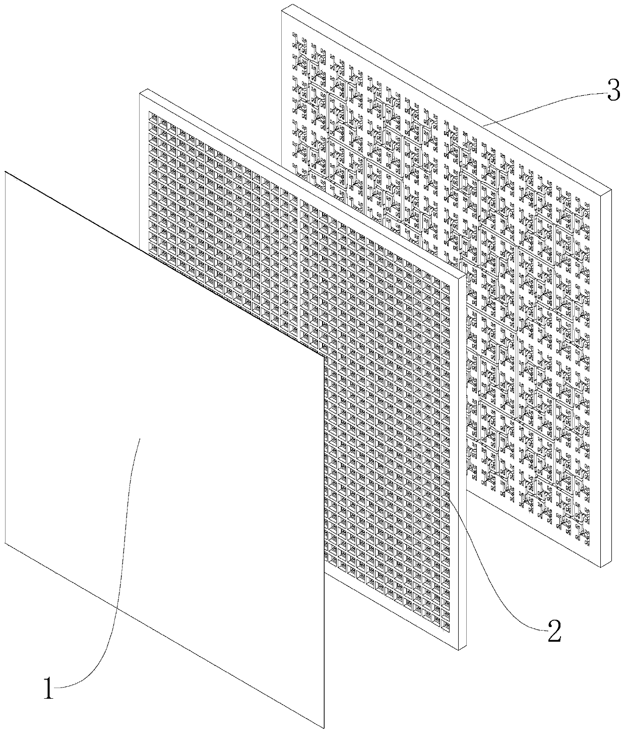
[0025] Example: such as figure 1 As shown, a wide-band panel array antenna includes a polarization layer 1, a radiation layer 2, and a feed layer 3 stacked in order from top to bottom; the feed layer 3 is used to convert a single TE10 mode into a multi-channel power The same TE10 mode signal with the same phase, and transmit multiple TE10 mode signals to the radiation layer 2, the radiation layer 2 is used to radiate the multiple TE10 mode signals from the feed layer 3 to free space, and the polarization layer 1 is used for The polarization direction of the electric field generated by the radiation layer 2 is rotated to reduce the side lobes of the E-plane pattern and the H-plane pattern.

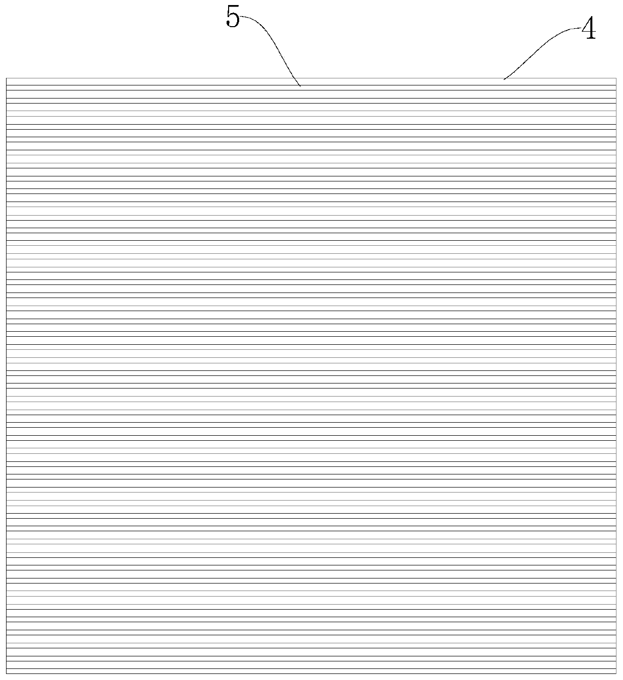
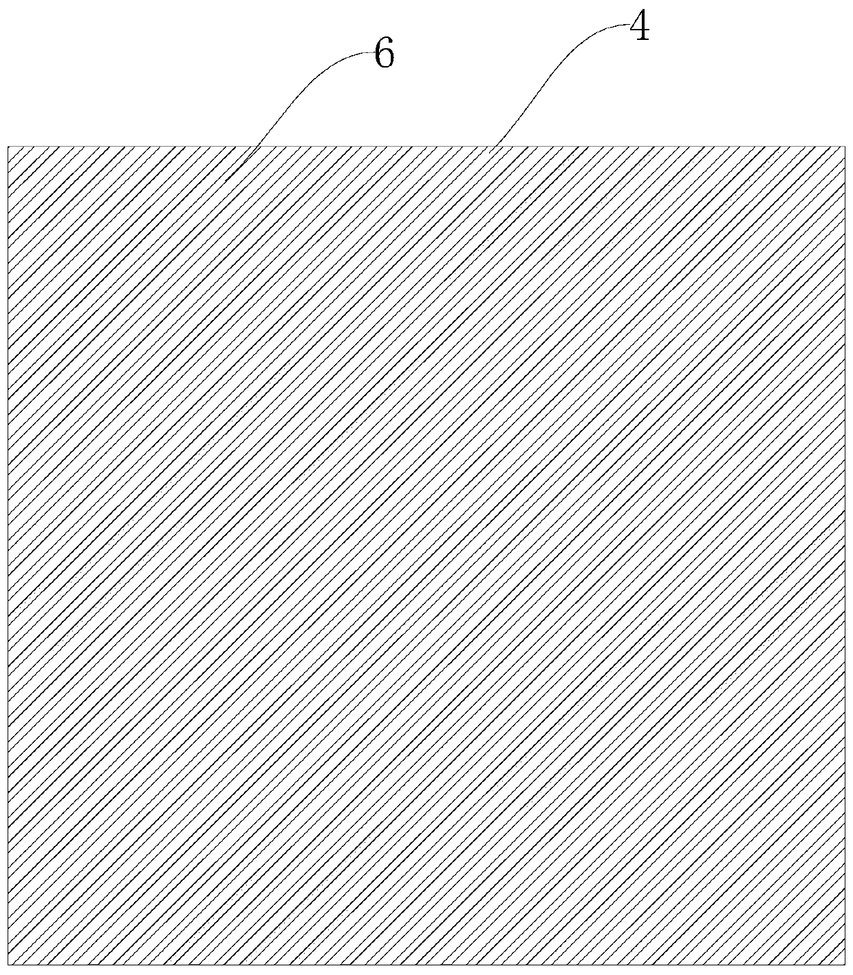
[0026] In this example, if figure 2 and image 3 As shown, the polarization layer 1 includes a dielectric substrate 4, a first metal layer disposed on the lower surface of the dielectric substrate 4, and a second metal layer disposed on the upper surface of the dielectric substrate 4. Th...


PUM


Abstract

The invention discloses a broadband planar array antenna, which comprises a polarization layer, a radiation layer and a feed layer which are sequentially stacked from top to bottom. The feed layer isused for converting a single TE10 mode into multiple TE10 mode signals with the same power and the same phase, and transmitting the multiple TE10 mode signals to the radiation layer; the radiation layer is used for radiating the multiple TE10 mode signals from the feed layer to a free space; and the polarization layer is used for enabling the electric field polarization direction generated by theradiation layer to rotate, so that side lobes of an E-plane directional diagram and an H-plane directional diagram are reduced. The antenna has the advantages of high gain and efficiency and low processing cost on the basis of low sidelobe.

Description

technical field [0001] The invention relates to a panel array antenna, in particular to a broadband panel array antenna. Background technique [0002] The amount of communication data per unit time in the modern information society is increasing, and the spectrum resources are becoming increasingly tight. The low end of the microwave frequency band is already very crowded. The millimeter wave frequency band has a pure electromagnetic environment and broadband available spectrum resources. It has become a high-speed era. The best choice for communication systems. The E-Band frequency band is a frequency band with a frequency around 80GHz. The actual allocated frequency bands are 71-76GHz and 81-86GHz. The total available bandwidth is 10GHz, which can meet the 10-20Gbps base station backhaul requirements in the 5G era. The E-Band frequency band is the most widely used frequency band in the current millimeter wave frequency band. [0003] In a wireless communication system, t...

Claims


Application Information

Patent Timeline
Patent Type & Authority Applications(China)
IPC IPC(8): H01Q21/06H01Q1/36H01Q1/38H01Q1/50H01P5/18
CPCH01Q21/061H01Q1/36H01Q1/38H01Q1/50H01P5/181H01P5/082H01Q21/064H01Q15/246H01Q21/0006H01Q1/422H01Q9/045H01Q13/26H01Q21/005H01Q21/0068H01Q21/0087
Inventor 尤阳黄季甫张玲尤清春陆云龙
Owner NINGBO UNIV
Why Eureka
Try Eureka