Supercharge Your Innovation With Domain-Expert AI Agents!

Permanent magnet motor rotor

A permanent magnet motor and rotor technology, applied in asynchronous induction motors, magnetic circuit rotating parts, magnetic circuits, etc., can solve the problems of complicated structure, decreased magnetic performance of permanent magnets, increased weight, etc., to achieve lightweight design, The effect of reducing the risk of demagnetization and improving the efficiency of the motor

Inactive Publication Date: 2020-08-28
NANJING UNIV OF AERONAUTICS & ASTRONAUTICS
View PDF2 Cites 2 Cited by
  • Summary
  • Abstract
  • Description
  • Claims
  • Application Information

AI Technical Summary

Problems solved by technology

[0004] However, rare earth permanent magnets are generally conductive. When the magnetic flux passing through the permanent magnet changes, an electric potential will be induced in the permanent magnet, thereby generating eddy currents. The thermal effect of the eddy currents will cause the permanent magnets to heat up.
The permanent magnet is more sensitive to temperature, the temperature rise will cause the magnetic performance of the permanent magnet to decline, and the temperature rises to the temperature resistance limit of the permanent magnet, and the permanent magnet will be permanently demagnetized
During the operation of the permanent magnet motor system, its armature current often contains certain harmonic components, and the harmonic magnetic field speeds generated by these harmonic components are not synchronous, which will cause eddy current losses on the permanent magnets
Generally speaking, the loss of the permanent magnet motor is mainly concentrated on the stator. The stator of the permanent magnet motor is designed with a cooling system, while the loss of the rotor of the permanent magnet motor is relatively limited. Setting the cooling system on the rotor will lead to complicated structure and increased weight. There is no special cooling system on the rotor, which will cause heat to accumulate on the permanent magnets, resulting in an increase in the temperature of the permanent magnets and increasing the risk of permanent magnet demagnetization

Method used


Image

  • Permanent magnet motor rotor
  • Permanent magnet motor rotor
  • Permanent magnet motor rotor

Examples


Embodiment Construction

[0027] The technical solution of the invention will be described in detail below in conjunction with the accompanying drawings.

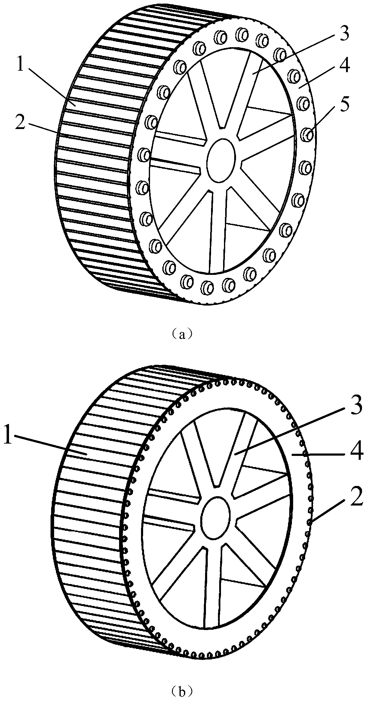
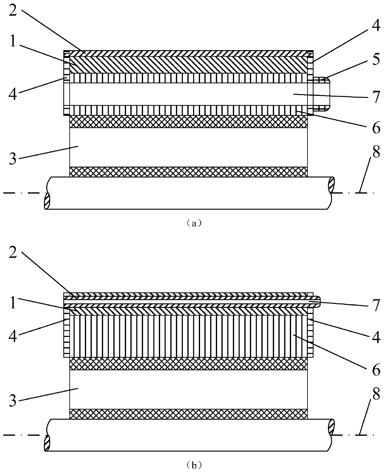
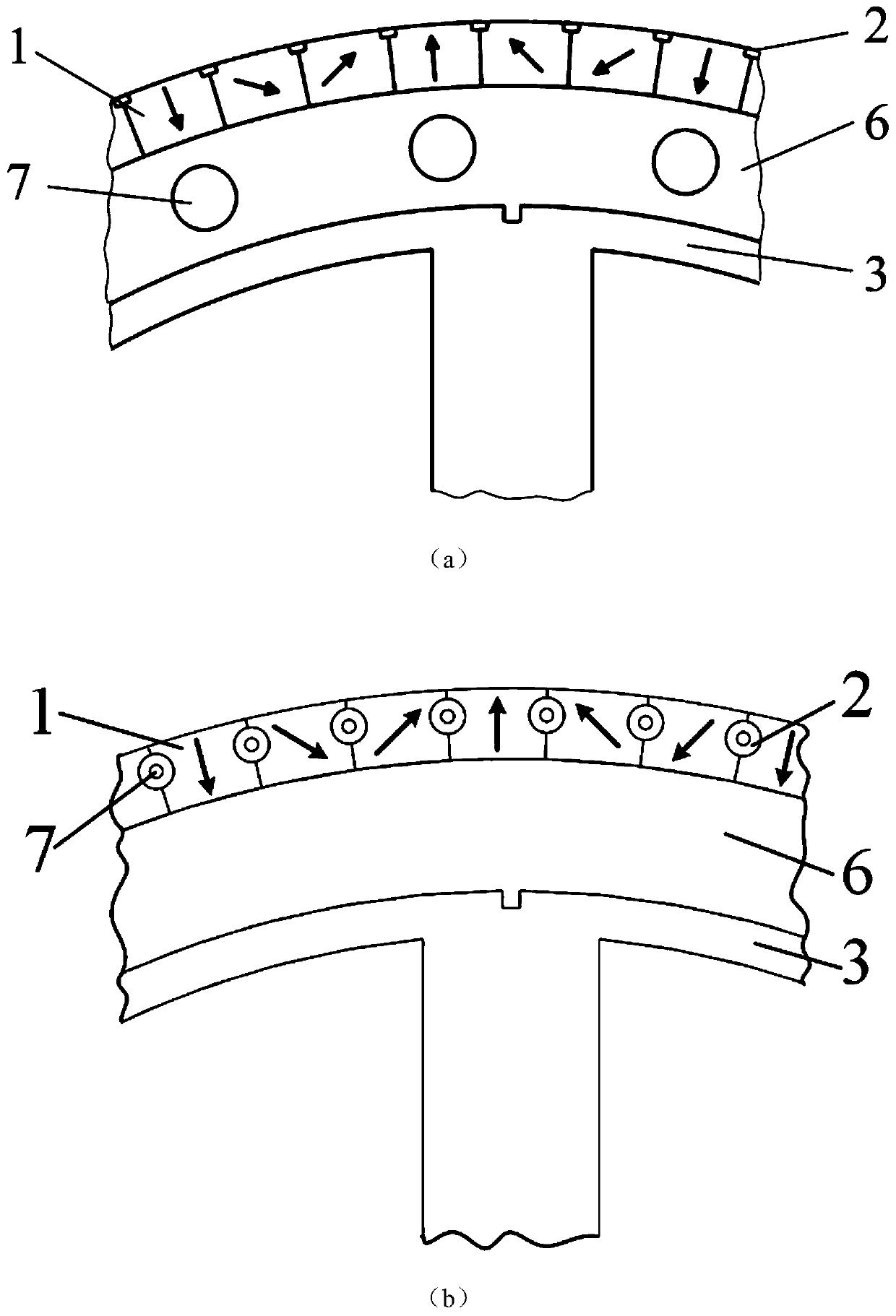
[0028] The invention provides a lightweight and low-loss permanent magnet motor rotor, which includes a permanent magnet, a rotor yoke, a rotor bracket, a damping winding and an air nozzle; the damping winding is a squirrel-cage damping winding, which is installed on the surface of the rotor The permanent magnet is installed on the rotor yoke, the rotor is provided with an axial air channel along the axial direction, the two ends of the rotor yoke are provided with end plates, and the end plate at one end is provided with an air nozzle.

[0029] Further, the permanent magnets are surface-mounted on the rotor yoke. If the permanent magnets are placed in a Halbach array, the rotor yoke is eliminated, and the permanent magnets are directly installed on the rotor bracket.

[0030] Further, the squirrel-cage damping winding is composed of a damping bar a...


PUM


Abstract

The invention relates to a permanent magnet motor rotor suitable for an aircraft electric propulsion system. The rotor comprises a permanent magnet, a rotor yoke, a rotor bracket, a mouse cage type damping winding, an air nozzle and the like, wherein the permanent magnet is installed on the rotor yoke, the rotor yoke is installed on the rotor bracket, the mouse cage type damping winding is installed on the surface of the rotor and serves as the installation tool of the permanent magnet, and can further be used for fixing the permanent magnet, the end plate of the damping winding serves as a balance end plate and is used for rotor dynamic balance correction, the rotor is provided with an axial air channel, the air channel is arranged on the rotor yoke or the rotor bracket, a hollow dampingwinding can also be adopted to form the air channel, the air inlet of the air channel is not processed, the air outlet is provided with the air nozzle, and two ends of the air channel can generate pressure difference during rotation to generate self-suction effect. According to the invention, the rotor design scheme is simple in structure, the cooling effect of the permanent magnet motor rotor canbe improved without additional cooling equipment, the operation reliability of the permanent magnet motor for aircraft electric propulsion can be enhanced, and the rotor can also be applied to new energy automobiles, household appliances and other fields.

Description

technical field [0001] The invention relates to a lightweight and low-loss permanent magnet motor rotor, which belongs to the technical field of motors. Background technique [0002] Permanent magnet motors have the characteristics of high torque density and high efficiency, and have been widely used in new energy vehicles, household appliances, aerospace and other fields. At present, aircraft electrification is an important direction for the development of aviation technology, and advanced concepts and technologies such as multi-electric / all-electric aircraft and electric propulsion aircraft have been born. Sex and other aspects must meet higher requirements than the existing level. It is precisely because of its advantages that permanent magnet motors have become strong competitors in the field of aviation applications. [0003] Compared with electric excitation motors, the excitation magnetic potential of permanent magnet motors comes from permanent magnets, which can p...

Claims


Application Information

Patent Timeline
IPC IPC(8): H02K1/27H02K1/32H02K7/04H02K3/16H02K17/16
CPCH02K1/274H02K1/32H02K3/16H02K7/04H02K17/165
Inventor 张卓然陆嘉伟孔祥浩李进才花韫韬
Owner NANJING UNIV OF AERONAUTICS & ASTRONAUTICS
Features
  • R&D
  • Intellectual Property
  • Life Sciences
  • Materials
  • Tech Scout
  • Unparalleled Data Quality
  • Higher Quality Content
  • 60% Fewer Hallucinations
Learn More