
Novel radio frequency atom magnetometer and implementation method thereof

An atomic magnetometer and radio frequency technology, which is applied in the direction of the size/direction of the magnetic field, and the use of magneto-optical equipment for magnetic field measurement, etc., can solve the problems of radio frequency atomic magnetometer sensitivity drop, small measurement range, etc., and achieve simple operation and large measurement range big effect

Active Publication Date: 2020-09-01
HANGZHOU DIANZI UNIV +1
View PDF12 Cites 7 Cited by
  • Summary
  • Abstract
  • Description
  • Claims
  • Application Information

AI Technical Summary

Problems solved by technology

When the frequency of the alternating magnetic field to be measured is high, the traditional radio frequency atomic magnetometer requires a corresponding increase in the size of the static magnetic field, and an excessively large static magnetic field will cause the enhancement of the second-order Zeeman effect of the atom, resulting in the traditional radio frequency atomic magnetometer The sensitivity of the instrument decreases
Therefore, the frequency measurement range of the traditional radio frequency atomic magnetometer to the alternating magnetic field is small, generally less than 1MHz

Method used


Image

  • Novel radio frequency atom magnetometer and implementation method thereof
  • Novel radio frequency atom magnetometer and implementation method thereof
  • Novel radio frequency atom magnetometer and implementation method thereof

Examples


Embodiment Construction

[0054] The present invention is further analyzed below in conjunction with accompanying drawing.

[0055] A radio frequency coil is used to generate a radio frequency field, so that the total frequency of the radio frequency field felt by the atoms is the absolute value of the frequency difference between the radio frequency field and the alternating magnetic field to be measured. At the same time, a stable and known static magnetic field is applied to the atoms to adjust the frequency of the radio frequency field. The Larmor precession frequency of the atoms is equal to the frequency of the total radio frequency field, thereby forming a magnetic resonance spectrum, and measuring the alternating magnetic field to be measured according to the magnetic resonance spectrum.

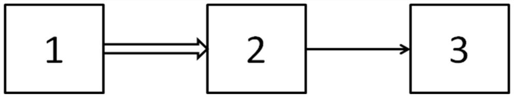
[0056] like figure 1 As shown, the radio frequency atomic magnetometer includes a laser light source 1, a weak magnetic field probe 2, and a signal processing circuit 3; the laser light source 1 is connected ...


PUM


Abstract

The invention discloses a novel radio frequency atom magnetometer and an implementation method thereof. According to the invention, the method comprises the steps: enabling the laser wavelength to bestable, and keeping resonance between the laser wavelength and the alkali metal atom ground state energy level; enabling a polaroid to be perpendicular to the direction of the laser beam to change laser into linearly polarized laser; enabling the linearly polarized laser to pass through the atomic gas chamber and to be received by the photoelectric detector, wherein the direction of the linearly polarized laser is parallel or vertical to the direction of the to-be-measured alternating magnetic field; enabling the static magnetic field to be stable and unchanged, wherein the direction is parallel to the linear polarization laser direction, and the radio frequency field direction is perpendicular to the to-be-measured alternating magnetic field direction; enabling the photoelectric detectorto detect the light intensity value change of all the linearly polarized lasers passing through the atomic gas chamber and outputting a voltage value, collecting the voltage value through the feedbackcontroller, and performing feedback control on the signal generator, so that the absolute value of the difference between the radio frequency field frequency and the to-be-measured alternating magnetic field frequency is equal to the Larmor precession frequency of alkali metal atoms; and calculating the frequency and the magnetic induction intensity of the to-be-measured alternating magnetic field according to the magnetic resonance spectrum. The method has the advantages of simple operation and large measurement range.

Description

technical field [0001] The invention belongs to the field of magnetic field measurement, and relates to a novel radio-frequency atomic magnetometer and a realization method thereof, which are used for measuring high-frequency alternating magnetic fields, thereby improving the measurement range of the radio-frequency atomic magnetometer. Background technique [0002] Radio frequency atomic magnetometer is an important branch of atomic magnetometer, mainly used to measure alternating magnetic field, which makes up for the defect that traditional atomic magnetometer can only measure static magnetic field, and makes the application of atomic magnetometer more extensive. At present, the traditional radio frequency atomic magnetometer mainly realizes the measurement of the alternating magnetic field to be measured by adjusting the static magnetic field so that its size and the frequency of the alternating magnetic field to be measured meet a certain proportional relationship. When...

Claims


Application Information

Patent Timeline
IPC IPC(8): G01R33/032
CPCG01R33/032
Inventor 梁尚清杨国卿李高翔黄光明
Owner HANGZHOU DIANZI UNIV
Learn More