In-phase power division filter based on slot line and microstrip

A filter and slot line technology, which is applied in the field of microwave passive devices, can solve the problems of general matching characteristics of balun filters, increased design complexity, and high design complexity, and achieves easy processing and integration, simple structure, and balanced Good effect

Active Publication Date: 2020-09-01
NANJING NORMAL UNIVERSITY
View PDF7 Cites 4 Cited by
  • Summary
  • Abstract
  • Description
  • Claims
  • Application Information

AI Technical Summary

Problems solved by technology

[0003] Document 1 (J.X.Xu and X.Y.Zhang, "Compact LTCC balun with bandpass response based on marchand balun," IEEE Microw Wireless Compon. Lett., vol.26, no.7, pp.493-495, Jul.2016.) based on low temperature Co-fired ceramic technology (LTCC), using Marchand balun to design a miniaturized balun filter, however, the design complexity of this process is high, and the insertion loss is large
[0004] Literature 2 (G.-Q.Zhang, J.-X.Chen, J.Shi, H.Tang, H.Chu, and Z.-H.Bao, "Design of multilayer balun filter with independently controllable dual passbands," IEEE Microw .Wireless Compon.Lett.,vol.25,no.1,pp.10-12,Jan.2015.) Based on the multi-layer PCB technology, a cro

Method used


Image

  • In-phase power division filter based on slot line and microstrip
  • In-phase power division filter based on slot line and microstrip
  • In-phase power division filter based on slot line and microstrip

Examples


Embodiment 1

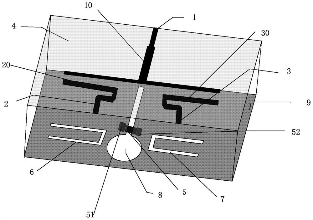
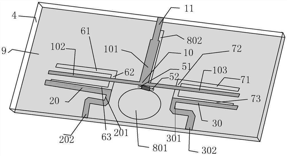
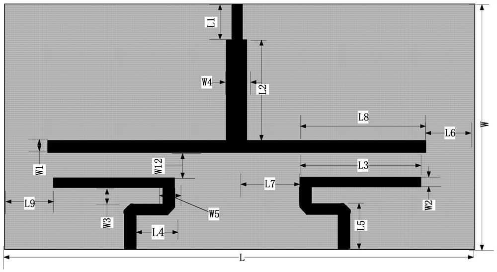
[0037] The three-dimensional structure of the codirectional power division filter based on the slot line and the microstrip multimode resonator is as follows figure 1 As shown, the top view is as figure 2 As shown, the relevant dimensions and specifications are as follows image 3 shown. The dielectric substrate 4 used has a relative permittivity of 3.55, a thickness of 0.508 mm, and a loss tangent of 0.0027. combine image 3 , The size parameters of the co-directional power dividing filter are as follows: L=50mm, L1=6mm, L2=11mm, L3=12.5mm, L4=4mm, L5=5mm, L6=5.7mm, L7=6.5mm, L8=12.8 mm, L9=6mm, W=27.61mm, W1=0.69mm, W2=0.5mm, W3=2mm, W4=1.38mm, W5=1.18mm, W12=2.23mm, R=4.2mm, L21=12.5mm, L31=6mm, W21=2.8mm, W22=0.22mm, W23=0.5mm, W30=20mm, W31=1.945mm, W32=6.97mm, R1=240Ω.

[0038] The co-directional power divider filter in this example is modeled and simulated in the electromagnetic simulation software HFSS.18.0. Figure 5 It is the S-parameter simulation diagram of ...


PUM


Abstract

An in-phase power division filter based on a slot line and a microstrip, disclosed by the present invention, comprises a rectangular dielectric substrate (4), a metal grounding plate (9) is arranged on the lower surface of the rectangular dielectric substrate (4), and an input port feeder line (1), a first output port feeder line (2) and a second output port feeder line (3) which are symmetricallydistributed, are arranged on the upper surface of the dielectric substrate (4). A T-shaped microstrip line (10) is positioned in the middle of the dielectric substrate, the first microstrip line (20)and the second microstrip line (30) are respectively connected with the first output port feeder line (2) and the second output port feeder line (3), and the continuous right-angle bent slot lines (6) and (7) and circular fan slot lines (8) are etched on the metal grounding plate (9). The isolation resistors (5) are arranged below the joints of the circular fan slot lines (8), and the metal columns are distributed at the two ends of each isolation resistor (5) respectively. The slot line in-phase power dividing filter of the present invention is high in selectivity, good in port matching characteristic and small in phase deviation.

Description

technical field [0001] The invention relates to the technical field of microwave passive devices, in particular to an in-phase power division filter based on slot lines and microstrips. Background technique [0002] In recent years, modern wireless communication systems have flourished, increasing the demand for miniaturized, low-cost, multifunctional microwave devices. Among them, the non-inverting power divider filter, as a multifunctional device integrating signal filtering and balanced and unbalanced signal conversion functions, has attracted more and more attention. A high-performance non-inverting power divider filter can not only effectively reduce the size of the system, but also simplify the complexity of system design, thereby further realizing the low-cost, high-performance, and miniaturized design of the wireless communication system. [0003] Document 1 (J.X.Xu and X.Y.Zhang, "Compact LTCC balun with bandpass response based on marchand balun," IEEE Microw Wirel...

Claims


Application Information

Patent Timeline
IPC IPC(8): H01P1/203H01P5/10H01P5/16
CPCH01P1/20381H01P5/1007H01P5/16
Inventor 张钢陈媛杨欣茹汤礼铭焦飞
Owner NANJING NORMAL UNIVERSITY
Why Eureka
Try Eureka