Direct cooling machine
A technology of direct cooling and chiller, which is applied in refrigerators, adsorption machines, refrigeration and liquefaction, etc. It can solve the problems that the heat of sewage and waste water cannot be effectively used, and the heat source cannot be driven by industrial sewage and waste water, so as to achieve easy deposition and realization The effect of concentration reduction
- Summary
- Abstract
- Description
- Claims
- Application Information
AI Technical Summary
Problems solved by technology
Method used
Image

Examples
specific Embodiment approach 1
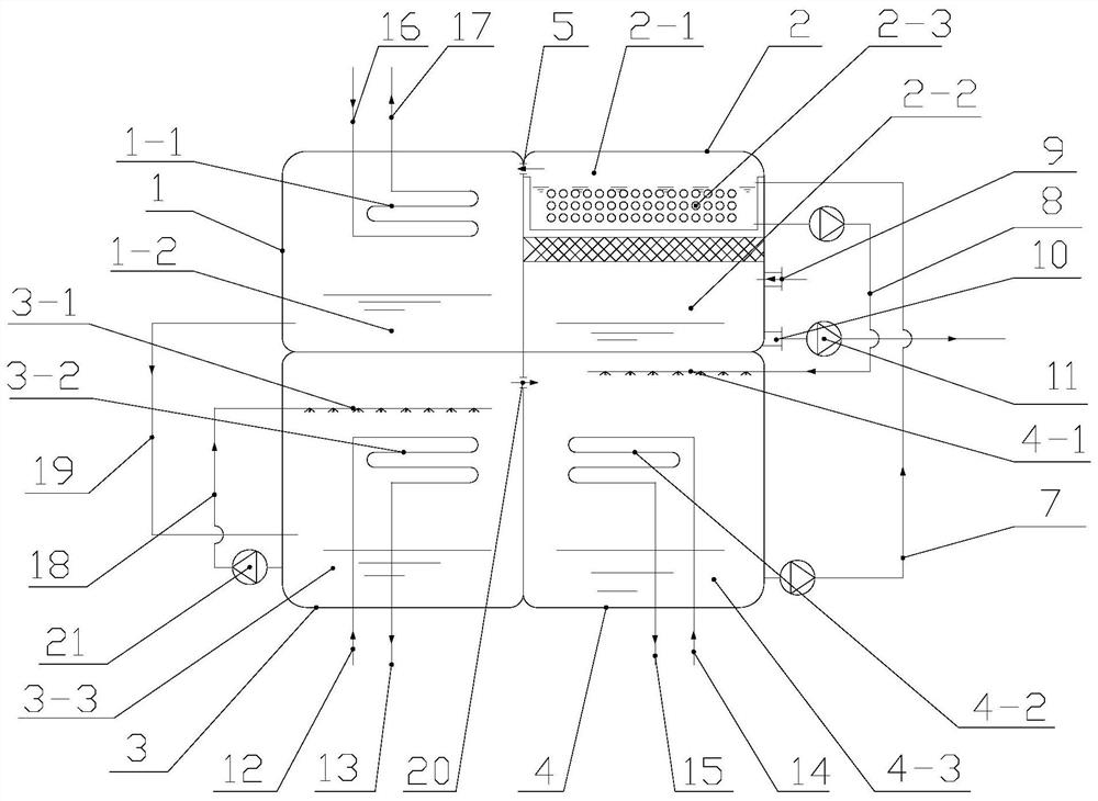
[0025] Specific implementation mode one: combine Figure 1~6 Describe this embodiment, direct cooling machine, it comprises condenser 1, generator 2, evaporator 3 and absorber 4, and the first vapor channel 5 is opened between condenser 1 and generator 2,
[0026] Described generator 2 comprises the lithium bromide solution cavity 2-1 that is positioned at the top and is positioned at the flash chamber 2-2 of lithium bromide solution cavity 2-1 below, and the top of generator 2 is communicated with and is provided with vacuum pump 6, by vacuum pump 6 generator 2 The interior is vacuumed, and the upper part of the lithium bromide solution chamber 2-1 is communicated with the lower part of the absorber 4 through the dilute lithium bromide solution pipe 7, and the dilute lithium bromide solution in the absorber 4 is transported to the lithium bromide solution chamber 2- through the dilute lithium bromide solution pipe 7. 1, the lower part of the lithium bromide solution chamber 2...
specific Embodiment approach 2
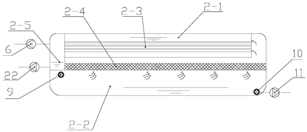
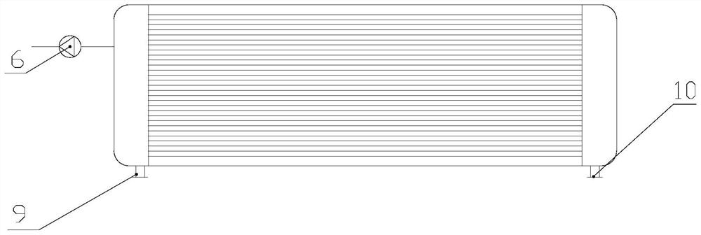
[0040] Specific implementation mode two: combination image 3 and 4 To illustrate this embodiment, the sewage water inlet pipe 9 is arranged vertically and its bottom end is located in the flash chamber 2-2. In this state, the sewage water inlet pipe 9 can pass through the lithium bromide solution chamber 2-1 and enter the flash chamber 2-2, or can be located on the side of the lithium bromide solution chamber 2-1, as long as it does not affect the steam entering the lithium bromide solution chamber 2 The first heat exchange tube 2-3 in -1 is sufficient.
[0041] The number of lithium bromide solution chambers 2-1 is two, and they are relatively arranged on both sides of the sewage water inlet pipe 9, and the flash steam enters the lithium bromide solution chamber 2-1 through the opposite sides of the two lithium bromide solution chambers 2-1. heat exchange.
[0042] Other compositions and connections are the same as those in the first embodiment.
specific Embodiment approach 3
[0043] Specific implementation mode three: combination Figure 1-4 To illustrate this embodiment, the waste water can be blast furnace slag flushing water, which is used as a heat source for refrigeration, and the cold water produced can be used for blast furnace blast cooling nearby, so as to condense the water vapor in the blast furnace blast to achieve blast furnace blast dehumidification. Purpose. Because there are a lot of salts dissolved in the blast furnace slag washing water, when the slag washing water releases heat to the outside, it is easy to crystallize and precipitate and adhere to the surface of the heat exchange wall, causing problems such as corrosion and blockage of the heat exchange face. The lithium bromide refrigerating unit of the present invention cannot utilize the residual heat of the slag flushing water to refrigerate, causing this part of heat to be wasted in vain. The direct cooler of the application can effectively solve the problems existing in th...
PUM
 Abstract
Description
Claims
Application Information
 - R&D
- Intellectual Property
- Life Sciences
- Materials
- Tech Scout
- Unparalleled Data Quality
- Higher Quality Content
- 60% Fewer Hallucinations
Browse by: Latest US Patents, China's latest patents, Technical Efficacy Thesaurus, Application Domain, Technology Topic, Popular Technical Reports.
© 2025 PatSnap. All rights reserved.Legal|Privacy policy|Modern Slavery Act Transparency Statement|Sitemap|About US| Contact US: help@patsnap.com